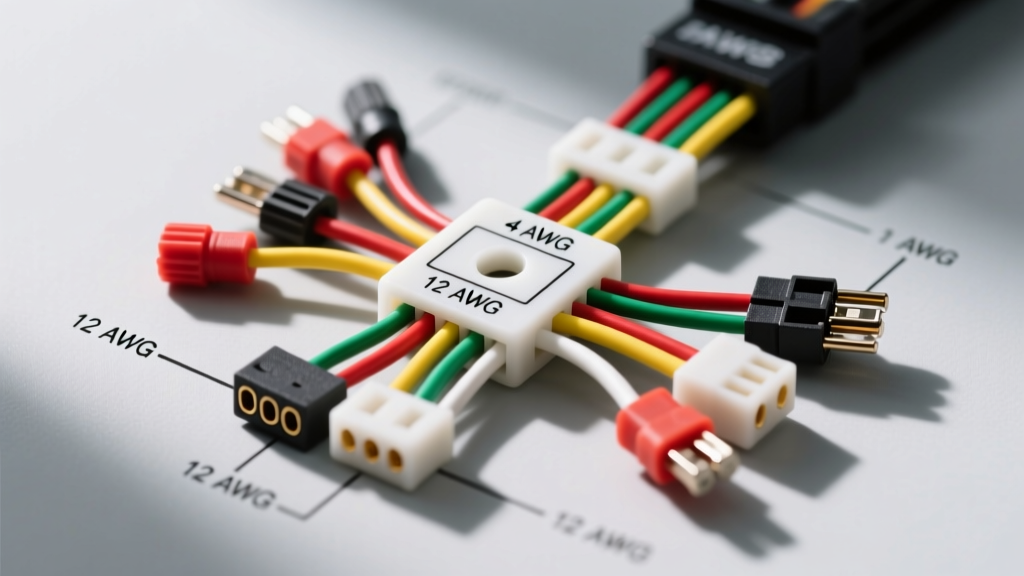
Introduction to 4-Pin Trailer Wiring Fundamentals
When towing light-duty loads such as utility trailers, jet skis, motorcycle carriers, or small boat trailers, a 4-pin flat connector is the undisputed industry standard. Unlike heavier 7-pin setups that accommodate electric brakes and auxiliary 12V power, trailer wiring diagrams 4 pin configurations are dedicated strictly to basic illumination: taillights, brake lights, and turn signals. For beginners, understanding the color codes, wire gauges, and grounding principles of this system is the difference between a safe, legal tow and a frustrating roadside electrical failure.
This guide breaks down the essential anatomy of the 4-pin flat harness, providing actionable installation advice, wire gauge specifications, and diagnostic steps to ensure your trailer lights function flawlessly every time you hit the road.
Standard 4-Pin Flat Connector Pinout & Color Codes
The 4-pin flat connector follows a strict color-code standard established by the Society of Automotive Engineers (SAE) and universally adopted by North American manufacturers. Whether you are looking at the vehicle-side plug or the trailer-side receptacle, the wire colors remain consistent.
| Pin Position | Wire Color | Function | Recommended AWG |
|---|---|---|---|
| Pin 1 (Exposed/Ground) | White | Chassis Ground Return | 14 AWG - 16 AWG |
| Pin 2 | Brown | Tail / Running Lights | 16 AWG - 18 AWG |
| Pin 3 | Yellow | Left Turn Signal & Brake | 16 AWG - 18 AWG |
| Pin 4 | Green | Right Turn Signal & Brake | 16 AWG - 18 AWG |
Note: The ground pin (Pin 1) is typically slightly wider or differently shaped on the molded rubber housing to prevent reverse-polarity insertion.
Understanding Wire Gauge (AWG) and Voltage Drop
One of the most common beginner mistakes is ignoring wire gauge. Most cheap, off-the-shelf trailer harnesses use 18 AWG (American Wire Gauge) wire for all circuits. While 18 AWG is sufficient for very short trailers (under 10 feet) pulling minimal amperage, it is highly susceptible to voltage drop over longer distances.
Voltage drop occurs when electrical resistance in the copper wire reduces the voltage reaching the trailer lights. If your vehicle outputs 13.5V at the alternator, an 18 AWG wire running 25 feet to the trailer rear may only deliver 10.5V to the incandescent bulbs, resulting in dim, unsafe lighting.
- 18 AWG: Acceptable for LED trailer lights (which draw less than 1 amp total) and short harnesses under 10 feet.
- 16 AWG: The recommended standard for most light-duty trailers using traditional incandescent bulbs.
- 14 AWG: Highly recommended for the White Ground Wire. Because the ground wire carries the combined return current for the running lights, brake lights, and turn signals, it experiences the highest electrical load. Upgrading the white wire to 14 AWG drastically reduces resistance and prevents backfeeding issues.
Vehicle-Side Installation: PWM and Powered Converters
If you are wiring a modern vehicle (typically 2010 or newer), you cannot simply splice into the factory taillight wires. Modern automotive electrical systems utilize Pulse Width Modulation (PWM) and multiplexed wiring to monitor bulb health and save energy. The vehicle's Body Control Module (BCM) sends rapid pulses of electricity to the taillights rather than a steady 12V stream.
If you wire a standard 4-pin trailer harness directly into a PWM circuit, two things will happen:
- The trailer lights will strobe or flicker erratically.
- The combined amperage draw of the vehicle and trailer lights will exceed the BCM's threshold, triggering a 'bulb out' warning on your dash or permanently frying the vehicle's lighting control module.
The Solution: You must use a Powered Taillight Converter (often branded as a ModuLite or Upgraded Heavy Duty ModuLite). This device uses the vehicle's taillight wires only as low-amperage signal triggers. The converter box draws heavy power directly from the vehicle's 12V battery via an inline fuse, bypassing the BCM entirely and providing a clean, steady 12V output to your 4-pin trailer connector. The etrailer.com Wiring FAQ heavily emphasizes the use of powered converters on all modern unibody SUVs and crossovers to protect sensitive CAN-bus networks.
The Golden Rule of Trailer Wiring: Grounding
According to diagnostic procedures outlined by AA1Car, over 80% of all trailer lighting failures are not caused by blown bulbs or broken wires, but by a poor ground connection. The white wire must have a flawless, bare-metal connection to the trailer's steel frame.
How to Create a Bulletproof Ground:
- Locate a solid frame point near the front of the trailer tongue, away from moving coupler parts.
- Remove all paint, rust, and powder coating using 80-grit sandpaper or a wire wheel until you expose shiny, bare steel.
- Crimp a #10 or #12 ring terminal onto the 14 AWG white wire. Use a ratcheting crimper to ensure a gas-tight mechanical bond; solder the joint if possible for maximum corrosion resistance.
- Use a Star Washer (internal or external tooth lock washer) between the bolt head and the ring terminal. The teeth will bite into the copper and steel, preventing vibration from loosening the connection.
- Apply Dielectric Grease over the completed terminal to seal out moisture and prevent galvanic corrosion.
Beginner Troubleshooting Decision Tree
When your trailer lights malfunction, use this systematic approach to isolate the fault. Always test the vehicle-side 4-pin plug first using a Digital Multimeter (DMM) before blaming the trailer wiring.
Symptom 1: Running lights work, but brake/turn signals do not.
- Cause: Blown fuse on the vehicle-side converter, or a severed Yellow/Green wire.
- Fix: Check the inline fuse near the battery for the powered converter. If intact, probe Pins 3 and 4 with a DMM while an assistant presses the brake pedal. If 12V is present at the plug but not at the trailer lights, trace the trailer harness for physical damage.
Symptom 2: Trailer running lights are dim, and brake lights cause the running lights to flash brightly (Backfeeding).
- Cause: A severely corroded or missing ground connection on the trailer frame.
- Fix: Without a dedicated ground path, the brake circuit attempts to ground itself through the running light circuit. Clean the white wire ground point on the trailer tongue and ensure every individual taillight assembly is also grounded to bare metal.
Symptom 3: Vehicle turn signals 'hyper-flash' when the trailer is connected.
- Cause: If you upgraded your trailer to LED lights, the drastically reduced amperage draw tricks the vehicle's flasher relay into thinking a bulb is burnt out.
- Fix: Install 50W 6-Ohm load resistors in parallel on the Yellow and Green turn signal wires, or replace the vehicle's flasher relay with an LED-compatible electronic flasher.
Routing, Protection, and Longevity
A perfectly wired harness will still fail if it is routed poorly. When running the brown, yellow, and green wires along the trailer frame, always use split-loom tubing to protect the insulation from road debris and UV degradation. Secure the loom every 12 to 18 inches using UV-resistant nylon zip ties or metal P-clips bolted to the frame.
Critical Warning: Never route trailer wiring near the exhaust system or brake actuator linkages. Exhaust heat will rapidly melt 16 AWG insulation, causing a dead short against the steel frame. Always leave a 'service loop' (a small, intentional slack) near the trailer tongue to prevent the wires from snapping taut during sharp turning maneuvers.
By adhering to these foundational principles, utilizing the correct AWG wire sizes, and respecting the grounding requirements of the 4-pin system, you ensure a reliable, legal, and safe towing setup for years to come. For deeper technical specifications on heavy-duty towing and electric brake controllers, refer to the SAE International Standards documentation on commercial and recreational vehicle electrical architectures.