Introduction: Bridging the Workbench and the Trailer Hitch
Automotive electrical technicians and trailer fabrication specialists require absolute precision, both in their diagnostic reference materials and their bench tools. This technical specification reference addresses two critical, interconnected elements of the trailer wiring workshop: the internal 5 pin soldering iron wiring diagram used to maintain and repair temperature-controlled soldering stations (featuring 5-pin DIN or GX12 Aviation connectors), and the standardized 5-way flat trailer connector pinout governed by SAE J1128 and J286 standards. Whether you are rebuilding a high-wattage Weller or Hakko-style soldering station for heavy-gauge automotive work, or wiring a surge-brake trailer harness from scratch, understanding the metallurgical and electrical specifications of both your tools and your targets is mandatory for a reliable, corrosion-free connection.
5 Pin Soldering Iron Wiring Diagram (Station to Handle)
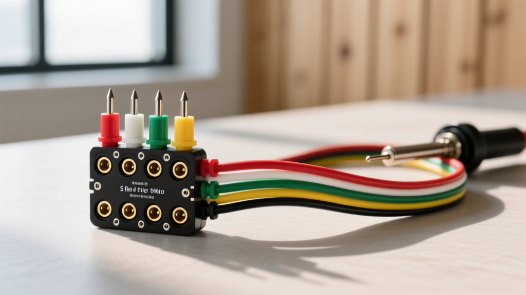
Professional temperature-controlled soldering stations utilized for automotive harness repair typically connect the base station to the iron handle via a 5-pin circular connector. This is usually a 5-pin DIN (Domino) or a 5-pin GX12 Aviation plug. The internal wiring of these irons separates the high-current heating element from the low-voltage thermocouple feedback loop to prevent signal interference and ensure precise thermal recovery when soldering 12 AWG trailer wires.
Standard 5-Pin Soldering Station Pinout
| Pin Number | Function | Recommended Wire Gauge | Insulation Requirement |
|---|---|---|---|
| Pin 1 | Heater Element (+) | 24 AWG Stranded | PTFE / Teflon (High Heat) |
| Pin 2 | Heater Element (-) | 24 AWG Stranded | PTFE / Teflon (High Heat) |
| Pin 3 | Thermocouple / Sensor (+) | 28 AWG Stranded (Shielded) | Kapton or Fiberglass Braid |
| Pin 4 | Thermocouple / Sensor (-) | 28 AWG Stranded (Shielded) | Kapton or Fiberglass Braid |
| Pin 5 | Chassis Ground / Shield Drain | 22 AWG Stranded | Silicone or PVC |
Repair Note: When repairing a broken 5 pin soldering iron cable, never use standard PVC wire for Pins 1 and 2. The internal temperatures near the ceramic heating element can exceed 200°C, which will melt PVC insulation and cause a short circuit that can destroy the station's TRIAC control board. Always use PTFE-insulated wire. For the thermocouple pins (3 and 4), use matched thermocouple extension wire (Type K or Type J, depending on the manufacturer) to prevent cold-junction compensation errors that will cause the iron to overheat or underheat during critical trailer harness soldering.
5-Way Flat Trailer Connector Pinout & Specifications
The 5-way flat trailer connector is the industry standard for light-to-medium duty trailers equipped with hydraulic surge brakes. The fifth pin is dedicated to the electric reverse lockout solenoid, which prevents the trailer brakes from engaging when the tow vehicle is placed in reverse. According to etrailer's SAE wiring guide and standard automotive practices, wire color coding and gauge sizing must strictly adhere to SAE J1128 specifications to prevent voltage drop and subsequent solenoid failure.
SAE 5-Way Flat Pin Configuration
| Pin | Function | SAE Wire Color | Minimum AWG | Max Continuous Amperage |
|---|---|---|---|---|
| 1 | Chassis Ground (White) | White | 10 AWG | 40A |
| 2 | Tail / Running Lights | Brown | 16 AWG | 10A |
| 3 | Left Turn / Stop Lamp | Yellow | 16 AWG | 10A |
| 4 | Right Turn / Stop Lamp | Green | 16 AWG | 10A |
| 5 | Auxiliary / Reverse Lockout | Blue | 12 AWG | 15A |
Technical Insight: Pin 1 (White Ground) is the most common failure point in trailer wiring. A 10 AWG ground wire is mandatory. If a 16 AWG wire is used for the ground, the combined amperage of the tail, brake, and turn signals will exceed the wire's capacity, leading to voltage drop, dim lights, and the backfeeding of current through other circuits (e.g., turn signals glowing dimly when the running lights are on).
Professional Soldering Techniques for 12-16 AWG Automotive Wire
While the Tekonsha technical resources and IPC/WHMA-A-620 standards generally recommend crimping for high-vibration automotive environments, soldering is entirely acceptable and highly reliable for sealed trailer harness repairs if executed with the correct metallurgical approach. The goal of soldering a trailer harness is not to provide mechanical strength—the mechanical strength must come from the physical splice or crimp barrel—but to provide a gas-tight, corrosion-proof electrical seal via capillary action.
Temperature and Flux Specifications
- Solder Alloy: Use 60/40 (Tin/Lead) or 63/37 (Eutectic) rosin-core solder. The rosin core (RMA - Rosin Mildly Activated) is essential for breaking down copper oxidation. Never use acid-core plumbing solder, as the residual acid will rapidly corrode the copper strands and cause galvanic degradation inside the harness.
- Iron Temperature: Set your 5-pin temperature-controlled station to 360°C - 380°C (680°F - 716°F) for 12 AWG and 14 AWG wires. The high thermal mass of 12 AWG copper requires rapid heat transfer to prevent the heat from traveling up the wire and melting the primary insulation.
- Pre-Tinning: Always pre-tin both the male and female wire ends before joining them. Apply the iron and feed the solder into the wire strands, not directly onto the iron tip. This ensures the flux activates exactly where the copper oxidation exists.
Environmental Sealing: Heat Shrink and Dielectric Grease
Once the solder joint has cooled and solidified, it must be sealed against moisture and road salt. Use dual-wall, adhesive-lined polyolefin heat shrink tubing with a 3:1 or 4:1 shrink ratio. When heated with a precision hot air gun (set to 120°C), the inner thermoplastic adhesive layer melts and flows into the wire strands, creating a waterproof barrier that prevents capillary wicking of moisture down the length of the trailer harness. Finally, pack the exterior connector cavity with a high-viscosity dielectric grease (such as Nyogel 760G) to displace oxygen and prevent fretting corrosion on the brass or nickel-plated terminals.
Troubleshooting Common 5-Way Trailer Wiring Faults
Use this diagnostic matrix to isolate faults in 5-way flat trailer harnesses using a digital multimeter (DMM) and your bench power supply.
| Symptom | Probable Cause | Diagnostic Fix / Action |
|---|---|---|
| Surge brakes lock up when vehicle is placed in reverse. | Pin 5 (Blue) circuit is open, or reverse lockout solenoid is seized. | Verify 12V+ at Pin 5 on the vehicle side while in reverse. If voltage is present, test solenoid coil resistance (typically 4-8 ohms). |
| Turn signals blink rapidly on the tow vehicle dash. | High resistance ground or blown trailer bulb causing hyper-flash. | Check Pin 1 (White) ground continuity to the trailer frame. Clean frame contact point to bare metal and apply dielectric grease. |
| Running lights work, but brake/turn signals do not. | Corroded pins on Pin 3 (Yellow) or Pin 4 (Green), or bad vehicle converter. | Probe the 4-way to 5-way adapter. If output is dead, replace the taillight converter module (required on vehicles with multiplex CAN-bus lighting). |
| Soldering iron fails to heat, LED on station blinks. | Broken thermocouple wire (Pin 3 or 4) inside the 5-pin aviation cable. | Open the handle and GX12 plug. Continuity test Pins 3 and 4. Resolder using high-temp Kapton-insulated wire. |
Authoritative References
For further reading on automotive electrical standards, soldering metallurgy, and trailer braking systems, consult the following industry resources: