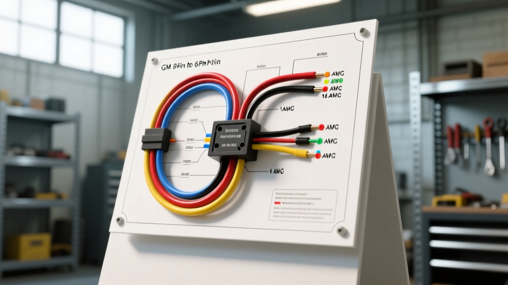
Why Tow-Rig LS Swaps Require Throttle Body Adapters
While Autoflowwire is the premier destination for trailer wiring diagrams and 7-pin harness installations, the modern heavy-duty tow-rig build frequently requires merging high-amperage trailer electrical systems with custom LS-swapped powertrains. When fabricating a custom car-hauler tractor or a heavy-duty recovery vehicle, builders often transplant a modern Gen IV 8-pin Drive-By-Wire (DBW) throttle body onto an older Gen III 6-pin harness (or vice versa). Understanding the gm 8 pin to 6 pin throttle body wiring diagram is an advanced, critical skill for ensuring your tow vehicle's engine management system can survive the harsh electrical environment created by trailer brake controllers and electric winch solenoids.
The high-amperage pulses from electric trailer brake modules and 12V car-hauler winches create massive Electromagnetic Interference (EMI) spikes. If the throttle body adapter harness is not built to exact specifications, these spikes will induce voltage fluctuations in the 5V reference circuits, leading to catastrophic throttle cut-offs while towing on steep grades. This guide provides the exact pinouts, AWG requirements, and fabrication steps to build a bulletproof adapter harness for your tow rig.
GM 6-Pin vs. 8-Pin Throttle Body Pinout Architecture
The fundamental difference between the early GM 6-pin (common on 2000-2005 LS1/LS2/Truck applications) and the later GM 8-pin (common on 2006+ LS3/L99/Gen IV applications) lies in sensor redundancy. The 8-pin design separates the 5V reference and ground circuits for Throttle Position (TP) Sensor 1 and TP Sensor 2. This fail-safe architecture allows the Electronic Control Module (ECM) to detect a short to ground or a short to voltage on one specific sensor circuit without immediately defaulting to limp mode.
When adapting an 8-pin throttle body to a 6-pin ECM harness, you cannot simply jumper the 5V references and grounds together at the connector. Doing so defeats the redundancy monitoring, and the ECM will throw a P0120 or P0220 code because it expects independent voltage return paths. Below is the master reference chart for both configurations.
| Pin (8-Pin) | Pin (6-Pin) | Function | Typical Wire Color | AWG Size |
|---|---|---|---|---|
| 1 (or A) | A | TAC Motor Control 1 (-) | Dark Blue / Tan | 18 AWG |
| 2 (or B) | B | TAC Motor Control 2 (+) | Light Blue / Grey | 18 AWG |
| 3 (or C) | D | TP Sensor 1 Signal | Blue / Dark Blue | 20 AWG (Shielded) |
| 4 (or D) | F | TP Sensor 1 5V Reference | Pink | 20 AWG |
| 5 (or E) | C | TP Sensor 1 Low Ref (Ground) | Black | 20 AWG |
| 6 (or F) | E | TP Sensor 2 Signal | Yellow | 20 AWG (Shielded) |
| 7 (or G) | Jumper to F | TP Sensor 2 5V Reference | Purple / Pink | 20 AWG |
| 8 (or H) | Jumper to C | TP Sensor 2 Low Ref (Ground) | White / Black | 20 AWG |
The EMI Factor: Trailer Brake Controllers and Sensor Noise
In a dedicated tow rig, the throttle body wiring harness is often routed through the firewall and down the frame rail, dangerously close to the trailer brake controller output wires and the 7-pin trailer connector harness. According to SAE J1113 standards for automotive electromagnetic compatibility, inductive loads like trailer electric brakes can generate voltage spikes exceeding 40V on a 12V system during PWM (Pulse Width Modulation) cycling.
If your TP Sensor 1 and TP Sensor 2 signal wires are not properly shielded and grounded at the ECM pigtail only, the EMI from the trailer brake controller will induce a false voltage reading on the throttle position sensors. The ECM will interpret this as the driver lifting off the throttle while the TAC motor is still commanding it open, resulting in a P2138 (Throttle/Pedal Position Sensor/Switch D/E Voltage Correlation) code and an immediate reduction in engine power—extremely dangerous when pulling a heavy trailer up a mountain pass.
Step-by-Step Installation: Building the Adapter Harness
To safely adapt the GM 8-pin throttle body to a 6-pin harness for your tow rig, you must build a custom adapter pigtail that manages the redundant circuits correctly while maintaining EMI shielding.
Step 1: Depinning and Wire Prep
Never cut the factory OEM throttle body connector off. Purchase a replacement Delphi GT 150 / GT 280 or Molex MX150 8-pin pigtail. Strip the outer jacket back exactly 6 inches. For the sensor signal wires (Pins 3 and 6), carefully fold back the copper braided shielding. Do not nick the inner 20 AWG Teflon insulation.
Step 2: Splicing the TAC Motor Circuits
The Throttle Actuator Control (TAC) motor draws up to 15 amps peak during rapid throttle transitions. Use 18 AWG TXL (cross-linked polyethylene) high-temperature wire for the motor circuits. If your tow rig has an extended wheelbase and the harness run exceeds 6 feet, step up to 16 AWG to prevent voltage drop. Use an open-barrel copper crimp tool to join the 8-pin motor wires to the 6-pin harness. Seal the crimp with 3M dual-wall heat shrink tubing containing polyamide adhesive to prevent moisture ingress from road spray and trailer wash bays.
Step 3: Managing the 5V References and Grounds
This is where most LS swaps fail. Because the 6-pin ECM only provides one 5V reference and one sensor ground, you must split these circuits to feed the 8-pin throttle body.
- 5V Reference Split: Splice the 6-pin 5V reference wire into a Y-harness to feed both Pin 4 and Pin 7 on the 8-pin connector. Use a sealed, solder-sealed butt connector.
- Ground Split: Splice the 6-pin sensor ground to feed both Pin 5 and Pin 8.
- Crucial Shielding Step: The drain wire from the shielded signal cables must be pigtailed and grounded only at the ECM connector end. Do not ground the shield at the throttle body end, as this will create a ground loop with the engine block, amplifying alternator whine and trailer brake EMI.
Real-World Troubleshooting: P0120, P0220, and P2138 Codes
Even with a perfect physical adapter harness, tow rigs present unique electrical gremlins. Use this decision tree to diagnose DBW faults after your swap:
- Symptom: P2138 Code (Voltage Correlation) only when applying trailer brakes.
Cause: Ground loop between the trailer brake controller and the ECM sensor ground. The brake controller is likely grounded to a painted chassis bolt, forcing return current through the ECM sensor ground.
Fix: Relocate the trailer brake controller ground directly to the battery negative terminal or a dedicated, clean engine block ground stud. Ensure the 7-pin trailer connector ground (Pin 1) is also tied to a clean frame-to-battery ground. - Symptom: P0120 / P0220 (TP Sensor Circuit Malfunction) at idle.
Cause: The ECM is detecting that the combined 5V reference load is too high, or the redundant grounds are experiencing voltage offset.
Fix: Verify the resistance of your adapter harness. The combined resistance from the ECM pin to the TB pin must be less than 0.5 ohms. Check for crushed wires behind the intake manifold where heat and vibration degrade cheap splices. - Symptom: TAC Motor whining or sluggish throttle response.
Cause: Voltage drop on the 18 AWG motor wires due to excessive length or poor crimps.
Fix: Upgrade the TAC motor circuits to 16 AWG wire and verify the main ECM power and ground distribution blocks are free of corrosion.
Conclusion and Authoritative References
Adapting a GM 8-pin throttle body to a 6-pin harness is a common hurdle in custom tow-rig and car-hauler builds, but it requires meticulous attention to sensor redundancy and EMI shielding. By treating the DBW sensor circuits with the same respect as your trailer's electric brake harness, you ensure safe, reliable power delivery under heavy loads. For further reading on automotive electrical standards and LS swap harness fabrication, consult the SAE J1113 Electromagnetic Compatibility Standards and the Haynes GM Full-Size Trucks Repair Manual for OEM grounding schematics. Always verify your specific ECM pinout using factory service documentation before applying power to your custom harness.