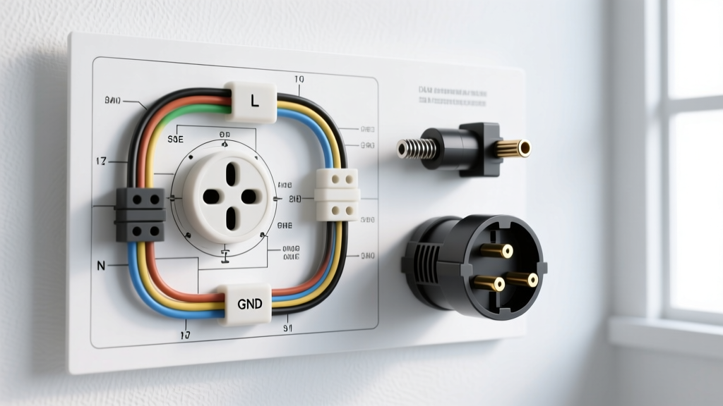
The Standard 7 Prong RV Plug Wiring Diagram
When towing recreational vehicles, horse trailers, or heavy-duty car haulers, the 7-way RV blade connector is the undisputed industry standard. Governed by the SAE J286 standard, this configuration provides dedicated circuits for electric brakes, 12V auxiliary power, reverse lights, and standard illumination. However, simply knowing the pinout is only half the battle. Selecting the correct physical connector and harness assembly is critical for long-term reliability, especially when dealing with high-amperage electric brake controllers and long wire runs.
Below is the definitive wiring diagram and pinout reference for the standard 7-prong RV blade plug (vehicle-side receptacle and trailer-side plug).
SAE J286 7-Way RV Blade Pinout Chart
| Pin Location | Function | Standard Wire Color | Minimum AWG | Max Amperage |
|---|---|---|---|---|
| Center | Ground (Chassis) | White | 10 AWG | 40A |
| Top Left | Tail / Running Lights | Brown | 12 AWG | 15A |
| Bottom Left | Left Turn / Stop | Yellow | 12 AWG | 15A |
| Bottom Right | Right Turn / Stop | Green | 12 AWG | 15A |
| Top Right | 12V Auxiliary / Charge | Black | 10 AWG | 30A |
| Middle Right | Electric Brakes | Blue | 10 AWG | 20A+ |
| Middle Left | Reverse Lights / Lockout | Purple | 12 AWG | 15A |
Product Comparison: Choosing the Right 7-Way Harness
Not all 7 prong RV plug wiring diagrams translate to the same physical hardware. The market is flooded with varying grades of connectors. Choosing the wrong type can lead to voltage drop, phantom braking, or complete harness failure. Here is a technical comparison of the primary harness configurations available.
1. Molded Pigtail vs. Screw-Terminal Plugs
Molded Pigtails: These feature wires that are injected directly into the PVC or TPE plug housing.
Pros: Superior IP67 water resistance; no internal terminal corrosion; strain relief is built into the jacket.
Cons: Field-unrepairable. If a wire breaks flush with the mold, the entire plug must be severed and replaced.
Best For: OEM replacements, marine environments, and users who prefer sealed, maintenance-free setups.
Screw-Terminal Plugs: These feature a hollow housing with brass or silver-plated screw terminals inside.
Pros: Fully serviceable in the field. You can strip, crimp, and re-terminate wires using ferrules if damage occurs.
Cons: Vulnerable to internal corrosion if the rubber grommet seal fails or if dielectric grease is not applied to the terminals.
Best For: Overlanders, commercial haulers, and DIYers who frequently modify or repair their trailer wiring on the road.
2. Contact Materials: Standard Brass vs. Silver-Plated
When reviewing product specifications, pay close attention to the blade material. Standard brass terminals are common in budget harnesses but are highly susceptible to galvanic corrosion and oxidation, which increases electrical resistance. For heavy-duty towing, always select silver-plated or tin-plated copper alloys. Silver plating maintains high conductivity even in high-humidity environments and ensures that the critical Blue (brake) and White (ground) pins do not suffer from voltage drop during emergency stopping scenarios.
3. Cable Configuration: Coiled vs. Straight Jacket
- Coiled (Curly) Cables: Excellent for preventing drag on the road and keeping the harness away from the hitch ball. However, the internal copper strands in coiled cables are subjected to repetitive torsional stress, which can lead to micro-fractures over time.
- Straight Heavy-Duty Jackets: Preferred for commercial and long-distance RV towing. When paired with a proper support bungee or cable retainer, straight cables with cross-linked polyethylene (XLPE) jackets offer superior abrasion resistance and internal wire longevity.
Wire Gauge Selection & Voltage Drop Mitigation
A common mistake when executing a 7 prong RV plug wiring diagram is utilizing 12 AWG wire for all circuits to save money. According to RVIA (Recreational Vehicle Industry Association) guidelines and standard electrical physics, voltage drop over a 25-to-30-foot trailer length will severely degrade the performance of electric brakes and 12V charging systems if the wire is too thin.
| Circuit | Standard AWG | Heavy-Duty / Long-Haul AWG | Reasoning |
|---|---|---|---|
| Ground (White) | 10 AWG | 8 AWG | The ground carries the return current for ALL other circuits. A weak ground causes backfeeding. |
| Electric Brakes (Blue) | 12 AWG | 10 AWG | Brake controllers can output 15-20A. Voltage drop reduces braking force. |
| 12V Aux (Black) | 12 AWG | 10 AWG | Required to prevent voltage drop when charging deep-cycle RV batteries or running a winch. |
| Lighting (Brown, Yellow, Green) | 14 AWG | 12 AWG | LED trailer lights draw minimal amperage; 14 AWG is generally sufficient. |
Expert Installation & Troubleshooting Insights
Even with a premium silver-plated, 10 AWG screw-terminal plug, poor installation techniques will compromise the system. Follow these expert protocols for terminating and maintaining your 7-way RV connector.
Termination Best Practices
- Use Ferrule Crimps: Never wrap bare stranded wire around a screw terminal. The clamping force will shear the outer strands, reducing the cross-sectional area and creating a high-resistance hot spot. Always use insulated bootlace ferrules crimped with a dedicated ferrule tool.
- Adhesive-Lined Heat Shrink: If using a molded pigtail and splicing it into an existing trailer harness, use dual-wall, adhesive-lined heat shrink butt connectors. The inner meltable adhesive creates a watertight seal that prevents capillary action from wicking moisture up the wire jacket.
- Torque Specifications: For screw-terminal plugs, tighten terminal screws to approximately 15-20 in-lbs. Over-torquing will strip the brass threads or snap the screw head; under-torquing will allow the wire to vibrate loose, causing arcing.
Real-World Failure Modes & Troubleshooting
Symptom: Phantom Braking or Pulsing Brake Controller
Cause: Corrosion or moisture bridging the gap between the Blue (Brake) pin and the Black (12V Aux) pin inside the plug housing.
Fix: Disassemble the plug, clean terminals with electrical contact cleaner, and pack the internal cavity with a non-conductive silicone dielectric grease. Ensure the rubber cord grip is tightly sealed.
Symptom: Tail Lights Dim When Turn Signals Are Activated
Cause: Inadequate ground on the Center (White) pin. The current is backfeeding through the tail light circuit to find an alternate path to the vehicle chassis.
Fix: Upgrade the White ground wire to 8 AWG. Clean the trailer frame grounding point down to bare metal, apply a zinc-rich primer to prevent rust, and secure with a star washer and stainless steel bolt. Refer to comprehensive Curt Manufacturing wiring guides for vehicle-specific grounding points on modern tow rigs with isolated PWM lighting modules.
By understanding the nuances of the 7 prong RV plug wiring diagram and selecting the appropriate harness architecture for your specific towing profile, you eliminate the most common electrical failures encountered on the road. Always prioritize terminal material quality and proper AWG sizing over aesthetic cable features.