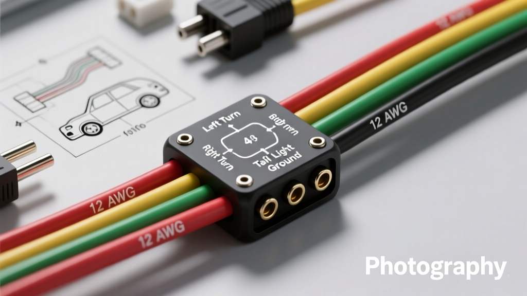
Understanding the 4-Way Flat Connector Standard
The 4-way flat connector is the undisputed standard for light-duty towing in North America, covering utility trailers, small boat trailers, and cargo haulers up to 3,500 pounds Gross Trailer Weight (GTW). When you study 4 wire trailer wiring diagrams, you are looking at a simplified but highly regulated lighting circuit governed by NHTSA's FMVSS 108 standards. Unlike heavier 7-pin setups that include auxiliary 12V power and dedicated electric brake circuits, the 4-pin system combines the brake and turn signal functions onto a single wire per side, relying on the vehicle's flasher relay or body control module (BCM) to pulse the combined circuit.
However, a diagram is only as good as the materials and techniques used to execute it. The most common cause of trailer lighting failure is not a blown bulb, but rather voltage drop, ground loops, and improper splicing. This guide provides the exact specifications, wire gauges, and installation protocols required to build a bulletproof 4-pin trailer harness.
4 Wire Trailer Wiring Diagram & Pinout Specification
Standardized color codes are critical for interoperability between different tow vehicles and trailers. The following table outlines the exact pinout, color code, and minimum American Wire Gauge (AWG) requirements based on SAE J1128 primary cable standards.
| Pin Position | Wire Color | Function | Min. AWG (Vehicle Side) | Min. AWG (Trailer Side) |
|---|---|---|---|---|
| 1 (Exposed Pin) | White | Chassis Ground | 12 AWG | 10 AWG |
| 2 | Brown | Tail / Running / Marker Lights | 16 AWG | 16 AWG |
| 3 | Yellow | Left Turn Signal / Stop Lamp | 16 AWG | 16 AWG |
| 4 | Green | Right Turn Signal / Stop Lamp | 16 AWG | 16 AWG |
Expert Note on Ground Wire Sizing: Notice that the White ground wire requires a heavier gauge (10-12 AWG) compared to the 16 AWG signal wires. The ground wire must carry the cumulative return current of every marker light, tail light, and brake light on the trailer. Using a thin 16 AWG wire for the main chassis ground creates resistance, leading to voltage drop and the infamous 'backfeed' issue where turn signals cause tail lights to pulse.
Selecting the Right Wire and Connectors
Never use cheap, PVC-insulated Copper-Clad Aluminum (CCA) wire for trailer harnesses. Aluminum expands and contracts at a different rate than copper, leading to loose crimps and internal corrosion. Always purchase GXL or TXL cross-linked polyethylene (XLPE) insulated wire. These automotive-grade wires resist high heat, abrasion, and chemical exposure far better than standard PVC.
For connections, banish 'Scotch-Loks' (T-taps) from your toolbox. T-taps sever copper strands and provide zero moisture sealing. Instead, use adhesive-lined, marine-grade heat shrink butt connectors. When heated, the internal thermoplastic adhesive melts and oozes out the ends, creating a completely waterproof seal that prevents capillary action from drawing moisture into the copper strands.
Step-by-Step Installation Guide
Step 1: Vehicle-Side Routing and Multiplexing Check
Before cutting a single wire on your tow vehicle, you must determine if your vehicle uses traditional 12V analog lighting or modern PWM (Pulse Width Modulation) multiplexed lighting. Most vehicles manufactured after 2015 use a BCM to control lighting with low-current PWM signals. If you tap directly into a PWM circuit with a standard 4-wire harness, you will experience hyperflashing, flickering, or potentially fry the vehicle's BCM.
For modern vehicles, you must install a powered tail light converter. This module draws power directly from the battery via a fused 12V feed (usually 12 AWG red wire) and uses the vehicle's tail light wires merely as low-current 'trigger' signals. Route the main harness along the frame rail, maintaining a minimum 12-inch clearance from the exhaust system to prevent the insulation from melting. Secure the loom every 18 inches using UV-resistant zip ties and adhesive-backed mounting pads.
Step 2: Making Bulletproof Splices
When extending or repairing harness wires, follow this exact crimping procedure:
- Strip: Use a precision wire stripper to remove exactly 1/4 inch of insulation. Do not nick the copper strands.
- Insert: Twist the strands lightly and insert them fully into the metal barrel of the heat-shrink butt connector until they bottom out.
- Crimp: Use a ratcheting crimping tool set to the correct die (usually marked 'Red' for 16-18 AWG). The tool must complete the full ratchet cycle before releasing.
- Pull-Test: Give both wires a firm tug. A proper crimp will withstand over 50 lbs of pull force.
- Seal: Apply heat with a heat gun (not a lighter) starting from the center and moving outward until the adhesive sealant visibly oozes from both ends.
Step 3: Establishing a True Chassis Ground
The ground connection is where 90% of trailer wiring issues originate. Do not simply wrap the white wire around a rusty bolt. Follow these steps for a permanent ground:
- Locate a solid steel section of the trailer frame near the tongue.
- Use 80-grit sandpaper or a wire wheel to strip away all paint, powder coating, and rust down to bare, shiny steel.
- Attach a heavy-duty, 10 AWG ring terminal to the white ground wire.
- Secure the ring terminal using a #10 or #1/4-20 self-tapping screw with a star washer. The star washer's teeth will bite into the bare metal, ensuring a low-resistance connection even if minor surface rust forms later.
- Smear a generous dab of dielectric grease over the top of the screw head and terminal to seal out moisture and road salt.
Troubleshooting Common 4-Pin Wiring Failures
Even with perfect diagrams, real-world conditions introduce variables. Use this diagnostic tree to solve the most common 4-pin issues:
Symptom: When the turn signal is activated, the tail lights on that side dimly flash in sync, or the opposite side's lights illuminate faintly.
Diagnosis: Ground loop / Backfeed.
Fix: The trailer lacks a dedicated ground path back to the tow vehicle via the white wire. The current is 'backfeeding' through the tail light circuit (brown wire) to find a ground. Clean the chassis ground points on both the trailer tongue and the tow vehicle hitch receiver. Ensure the hitch ball is not painted or heavily rusted, as the metal-to-metal coupling often serves as a secondary ground path.
Symptom: LED trailer lights hyperflash (blink rapidly) when connected to the tow vehicle.
Diagnosis: CAN-bus / Thermal Flasher Relay mismatch.
Fix: Traditional thermal flasher relays rely on the high current draw (approx. 2.1 amps per bulb) of incandescent bulbs to heat a bimetallic strip. LEDs draw less than 0.5 amps total. You must either replace the vehicle's flasher relay with an LED-compatible electronic flasher, or install 6-ohm, 50-watt load resistors in parallel on the yellow and green turn signal circuits to simulate the electrical load of incandescent bulbs.
Symptom: Running lights work, but brake/turn signals do not function at all.
Diagnosis: Blown vehicle-side fuse or failed converter module.
Fix: Check the tow vehicle's owner's manual for the specific 'Tow Module' or 'Trailer Stop/Turn' fuse in the under-hood PDC (Power Distribution Center). If the fuse is intact, probe the output side of the tail light converter with a multimeter. If there is 12V on the input trigger but 0V on the output, the internal solid-state relays of the converter have failed and the module must be replaced.
Final Inspection and Maintenance
After completing your 4 wire trailer wiring diagram installation, perform a full functional test with the trailer disconnected from the ball (to eliminate hitch-ground variables). Plug in the harness, turn on the headlights, and test both turn signals and the brake pedal. Finally, apply a light coat of dielectric grease to the male and female pins of the 4-way flat connector before mating them. This prevents galvanic corrosion between the brass pins and ensures reliable electrical contact for years of safe towing.