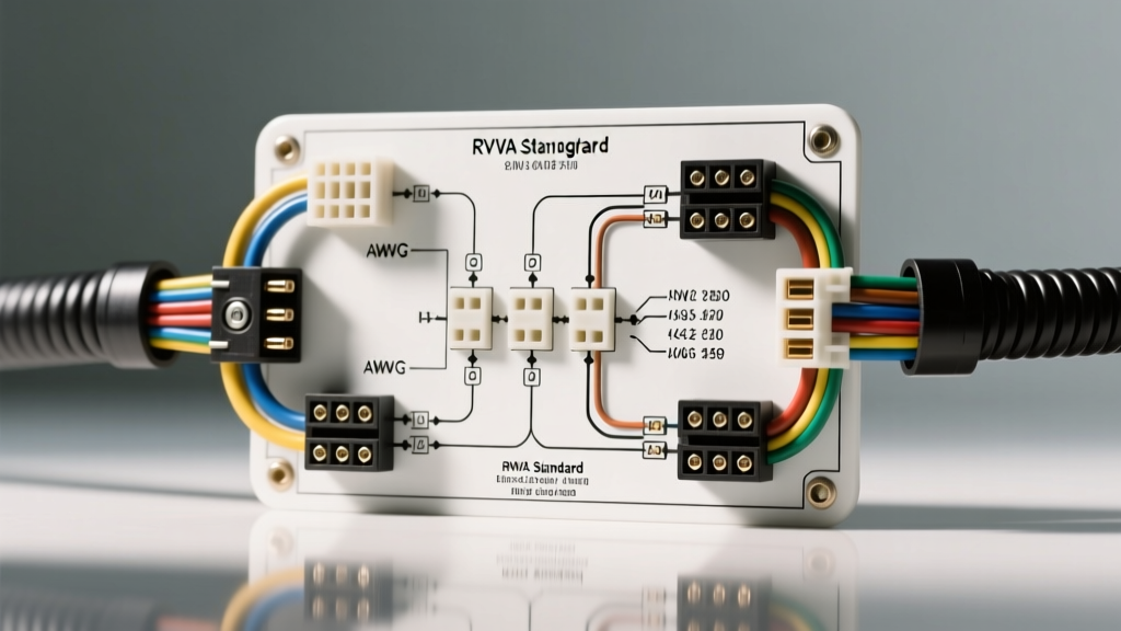
The Anatomy of the Seven Pin Trailer Wiring Diagram
When engineering a tow rig for heavy-duty trailers, fifth wheels, or multi-axle car haulers, the standard 4-way flat connector is entirely insufficient. The seven pin trailer wiring diagram serves as the critical nervous system for complex towing setups, providing dedicated circuits for electric brakes, 12V auxiliary power, and reverse lockout solenoids. In the recreational and light-commercial vehicle sector, the 7-way RV blade connector is governed by the Recreational Vehicle Industry Association (RVIA) and aligns with SAE J286 standards for trailer lighting and signaling. Understanding the precise pinout, wire gauge requirements, and pulse-width modulation (PWM) characteristics of this connector is mandatory for preventing voltage drop, brake latency, and alternator overload.
Master RVIA 7-Way Blade Pinout & AWG Specification Table
The following table outlines the industry-standard RVIA color codes, pin assignments, and minimum American Wire Gauge (AWG) requirements. Adhering to these AWG minimums is critical; undersizing wire on high-draw circuits like electric brakes or auxiliary charging will result in severe voltage drop and potential thermal failure.
| Pin | Function | RVIA Wire Color | Min AWG | Max Amperage / Circuit Notes |
|---|---|---|---|---|
| 1 | Ground (Chassis Return) | White | 8 AWG | Must handle combined return load of all lighting and brake circuits. |
| 2 | Electric Brakes | Blue | 10 AWG | Up to 20A+ depending on axle count. Carries PWM signal from controller. |
| 3 | Tail / Running Lights | Brown | 12 AWG | Typically 5-8A. Powers all marker, clearance, and tail lamps. |
| 4 | Left Turn / Stop | Yellow | 12 AWG | Combined stop/turn circuit. Max 10A per side. |
| 5 | Right Turn / Stop | Green | 12 AWG | Combined stop/turn circuit. Max 10A per side. |
| 6 | 12V Auxiliary / Battery Charge | Black | 10 AWG | Fused at 30A-40A. Used for trailer breakaway battery charging or 12V accessories. |
| 7 | Reverse Lights / Aux | Red (or Purple) | 12 AWG | Often routed to reverse lockout solenoids on hydraulic surge brake couplers. |
Electric Brake Circuit Engineering (Pin 2)
The blue wire on Pin 2 is arguably the most critical circuit in the entire seven pin trailer wiring diagram. Modern proportional brake controllers, such as the Tekonsha Prodigy P3, do not send a simple 12V DC steady-state current to the trailer brakes. Instead, they utilize a high-frequency Pulse Width Modulated (PWM) signal to proportionally apply the electromagnets based on the tow vehicle's deceleration rate.
Because electric brake magnets can draw up to 3.5 amps each, a triple-axle trailer with six brake assemblies can pull over 20 amps during a panic stop. If 12 AWG wire is used instead of the mandated 10 AWG (or 8 AWG for runs exceeding 25 feet), the resistance of the wire will cause a voltage drop. Using the voltage drop formula Vd = I × R × 2L, a 20A draw over 30 feet of 12 AWG copper wire results in a voltage drop of nearly 3.2 volts. This means the trailer brakes only receive 8.8V instead of 12V, drastically increasing stopping distance and causing the brake controller to falsely detect a 'trailer disconnect' or 'overload' fault due to the altered PWM feedback loop.
Grounding Architecture and the 'Ground Bounce' Phenomenon
Pin 1 (White) is the primary ground return path. A common and dangerous mistake in trailer manufacturing and DIY harness repairs is treating the trailer skin or chassis as an adequate ground return, relying on a single 12 AWG white wire to the tongue. This leads to 'ground bounce'—a phenomenon where high-amperage transients from the electric brakes seek the path of least resistance, often backfeeding through the delicate 12 AWG tail light wires (Pin 3) and blowing the tow vehicle's lighting control module (LCM) or BCM fuses.
Engineering Best Practice: The white ground wire must be a minimum of 8 AWG. It should be terminated with a #10 ring terminal, coated in dielectric grease, and bolted directly to a clean, bare-metal section of the main trailer frame tongue. Furthermore, a secondary ground strap (braided copper, minimum 10 AWG) should be installed across the trailer hitch ball mount to ensure redundancy in the event of corrosion between the tow vehicle receiver and the trailer coupler.
12V Auxiliary and Battery Charging (Pin 6)
The black wire on Pin 6 provides a direct 12V feed from the tow vehicle's alternator to the trailer. This circuit is primarily used to maintain the trailer's breakaway battery or power interior 12V accessories while in transit. This circuit must be protected by a 30-amp or 40-amp auto-resetting thermal circuit breaker mounted within 18 inches of the tow vehicle's battery positive terminal.
When wiring Pin 6, it is crucial to use an isolator or a voltage-sensitive relay (VSR) if the trailer features a large bank of deep-cycle lithium or AGM batteries. A deeply discharged trailer battery bank can pull upwards of 60 amps upon initial connection, which exceeds the standard 10 AWG wiring capacity and can overheat the tow vehicle's factory towing harness, melting the 7-way socket from the inside out.
7-Way RV Blade vs. 7-Way Round (SAE J560)
It is vital not to confuse the 7-way RV blade connector with the 7-way round pin connector used in heavy-duty commercial and agricultural applications. The 7-way round connector is governed by SAE J560 and utilizes entirely different color codes and pin assignments. For example, on a commercial 7-way round, Pin 1 is Ground (Black), Pin 4 is Stop Lights (Red), and Pin 7 is reserved for the trailer ABS system (Blue). Attempting to mate an RV blade harness to a heavy-duty round adapter without a dedicated rewiring junction box will instantly short-circuit the lighting and brake systems.
Diagnostic Matrix for 7-Way Harness Failures
When troubleshooting a faulty seven pin trailer wiring diagram, use this matrix to isolate the root cause using a digital multimeter (DMM) and a test load.
| Symptom | Probable Root Cause | Multimeter / Diagnostic Test |
|---|---|---|
| Trailer brakes lock up when headlights are turned on. | Shared ground fault. Pin 1 (White) is corroded or severed, causing brake current to backfeed through Pin 3 (Brown). | Test continuity between trailer frame and Pin 1 at the plug. Should be < 0.5 ohms. |
| Brake controller displays 'Overload' or 'Short Circuit'. | Pin 2 (Blue) wire insulation is chafed against the chassis, or brake magnets are internally shorted to the backing plate. | Disconnect trailer. Measure resistance between Pin 2 and Pin 1. Should read 1.5 - 3.0 ohms per axle. 0 ohms indicates a dead short. |
| Running lights flicker or dim when brakes are applied. | Voltage drop on the 12V supply or inadequate ground. The BCM is starving the lighting circuit to supply the brake PWM. | Measure voltage at Pin 3 (Brown) with lights on. Apply manual brake override. If voltage drops below 10.5V, upgrade ground wire. |
| Reverse lockout solenoid clicks but does not disengage. | Pin 7 (Red/Purple) is undersized (14+ AWG) or the solenoid coil is failing, drawing excessive amperage. | Check voltage at the solenoid while in reverse. Must be > 11.5V. Check amperage draw (typically 8-12A). |
Termination and Environmental Sealing Standards
The environment beneath a trailer is subjected to extreme vibration, road salt, and high-pressure water ingress. Standard vinyl electrical tape and butt connectors are strictly prohibited for any permanent repair on a seven pin trailer wiring diagram. All splices must be executed using adhesive-lined, dual-wall heat shrink tubing with an internal melt layer that creates a waterproof, strain-relieved seal. All junction box terminations must utilize nylon-insulated, crimp-style ring terminals, secured with stainless steel hardware and torqued to 40-50 in-lbs to prevent vibration-induced loosening. Finally, the 7-way plug receptacle itself should be packed with a non-conductive silicone dielectric grease to prevent galvanic corrosion between the brass pins and the copper wire terminals.