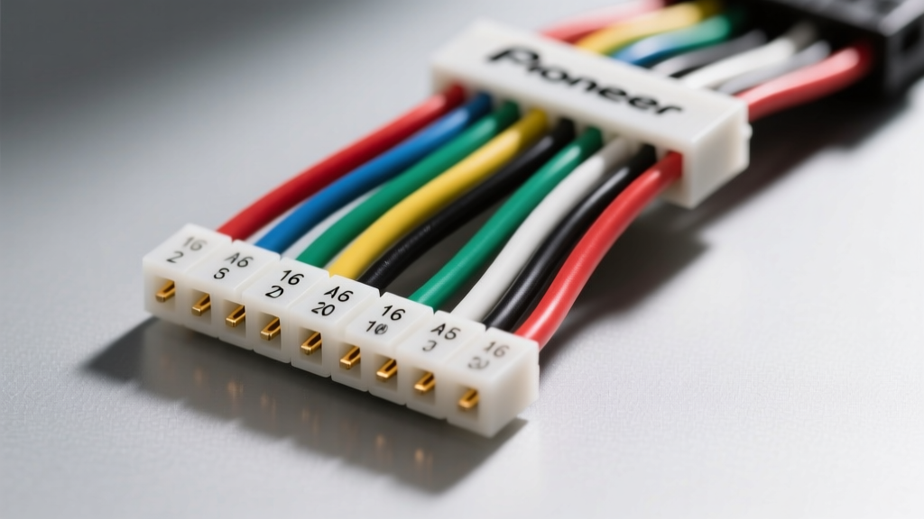
Integrating the 16 Pin Pioneer Wiring Harness in RV and Trailer Builds
While the 16 pin Pioneer wiring harness color code is primarily designed for standard automotive head unit installations, integrating aftermarket multimedia receivers into RVs, custom camper trailers, and fifth-wheel living spaces requires a specialized approach. Trailer and RV 12V DC electrical systems behave differently than standard passenger vehicles due to extended wire runs, high-draw appliances, and unique grounding topologies. Whether you are wiring a Pioneer AVH or DMH series head unit into an RV dashboard or configuring a reverse-trigger circuit for a trailer backup camera, understanding the exact pinout, AWG requirements, and relay isolation techniques is critical to preventing voltage drop and logic board failure.
In this complete wiring diagram walkthrough, we will decode the standard Pioneer 16-pin connector, adapt it for RVIA-compliant 12V DC systems, and detail the exact relay schematic required to safely trigger a trailer-mounted backup camera using the tow vehicle's 7-way plug.
Complete 16 Pin Pioneer Wiring Harness Color Code Chart
The standard Pioneer 16-pin ISO-style connector handles power, ground, illumination, and speaker outputs. Below is the definitive pinout chart, adapted with recommended AWG upgrades for trailer and RV applications where wire runs exceed 10 feet.
| Pin # | Wire Color | Function | Standard AWG | RV/Trailer Upgrade AWG |
|---|---|---|---|---|
| 1 | Yellow | Constant 12V (Battery/Memory) | 18 AWG | 12 AWG |
| 2 | Red | Accessory 12V (Ignition Switch) | 18 AWG | 14 AWG |
| 3 | Black | Chassis Ground | 18 AWG | 12 AWG |
| 4 | Orange | Illumination / Dimmer Trigger | 18 AWG | 18 AWG (No Change) |
| 5 | Blue | Power Antenna / Amp Turn-On | 18 AWG | 16 AWG |
| 6 | Purple/White | Reverse Gear Trigger (Camera) | 18 AWG | 18 AWG (Relay Isolated) |
| 7 | Mute/Phone | External Mute Control | 18 AWG | N/A |
| 8 | White | Front Left Speaker (+) | 18 AWG | 16 AWG |
| 9 | White/Black | Front Left Speaker (-) | 18 AWG | 16 AWG |
| 10 | Gray | Front Right Speaker (+) | 18 AWG | 16 AWG |
| 11 | Gray/Black | Front Right Speaker (-) | 18 AWG | 16 AWG |
| 12 | Green | Rear Left Speaker (+) | 18 AWG | 16 AWG |
| 13 | Green/Black | Rear Left Speaker (-) | 18 AWG | 16 AWG |
| 14 | Purple | Rear Right Speaker (+) | 18 AWG | 16 AWG |
| 15 | Purple/Black | Rear Right Speaker (-) | 18 AWG | 16 AWG |
| 16 | Light Green | Steering Wheel Control / Data | 18 AWG | 18 AWG |
RV & Trailer Specific Wiring Walkthroughs
1. Managing Voltage Drop on Long 12V DC Runs
According to RVIA (Recreation Vehicle Industry Association) ANSI/RVIA LV standards, 12V DC circuits in RVs must be sized to prevent a voltage drop exceeding 3% under maximum load. The factory 18 AWG wires on the Pioneer 16-pin pigtail are sufficient for a standard car dashboard where the battery is less than 6 feet away. In a travel trailer or Class C motorhome, the 12V DC distribution bus bar or battery bank may be 20 to 30 feet away.
If you use 18 AWG wire for the Constant 12V (Yellow) and Ground (Black) over a 25-foot run, the resistance will cause a severe voltage drop. When the head unit's internal amplifier spikes during heavy bass notes, the voltage at the head unit will drop below 11.2V, causing the Pioneer receiver to endlessly boot-loop or corrupt its EEPROM memory.
The Fix: Cut the Yellow and Black wires within 6 inches of the 16-pin connector. Solder and heat-shrink a splice to 12 AWG stranded primary wire for the remainder of the run to the RV's DC fuse panel. Install a 10A ATC/ATO blade fuse within 18 inches of the battery positive terminal, as mandated by SAE J1113 electrical safety guidelines.
2. Trailer Backup Camera Reverse Trigger Integration
Pin 6 (Purple/White) is the reverse trigger wire. When this wire receives +12V, the Pioneer head unit automatically mutes audio and switches the display to the rearview camera RCA input. In a trailer towing scenario, you want the camera mounted on the rear of the trailer to activate when the tow vehicle is shifted into reverse.
Critical Warning: The Pioneer Purple/White trigger circuit is a low-amperage logic input designed to handle a maximum of 300mA. Trailer lighting circuits, especially those with incandescent bulbs or long wire runs experiencing back-EMF, can easily spike and fry the head unit's internal logic board. You must never connect the Purple/White wire directly to a trailer's reverse light circuit or a 7-way plug pin.
Step-by-Step: Wiring the Reverse Trigger via Automotive Relay
To safely bridge the tow vehicle's reverse signal to the Pioneer harness inside the RV or truck cabin, use a standard Bosch-style 12V 30A SPDT automotive relay.
- Identify the Reverse Signal: Using a digital multimeter (DMM), probe the 7-way RV plug on the tow vehicle. Locate the Reverse Light pin (typically the Center Pin or Pin 7, depending on the SAE J286 configuration). Verify it reads +12V only when the vehicle is in reverse.
- Wire Relay Pin 86 (Coil +): Connect this to the +12V Reverse signal from the 7-way plug or the tow vehicle's reverse light tail wire.
- Wire Relay Pin 85 (Coil -): Connect this to a clean, bare-metal chassis ground.
- Wire Relay Pin 30 (Common): Connect this to a fused +12V Constant or Accessory source inside the cabin.
- Wire Relay Pin 87 (Normally Open): Connect this directly to the Pioneer Purple/White (Pin 6) wire.
When the tow vehicle is put in reverse, the relay coil energizes, safely passing clean +12V from Pin 30 to Pin 87, triggering the Pioneer camera view without risking back-voltage damage to the receiver.
Troubleshooting RV Head Unit Electrical Faults
Even with the correct 16 pin Pioneer wiring harness color code mapped out, trailer environments introduce unique electrical gremlins. Use this decision tree to diagnose common issues:
- Symptom: Head unit shuts off randomly when trailer marker lights or water pump turns on.
Cause: Ground loop or shared ground path. The 18 AWG Black wire is likely grounded to a chassis point shared with high-draw RV appliances.
Fix: Run a dedicated 12 AWG Black ground wire directly from the head unit to the main DC negative bus bar. Do not rely on the aluminum trailer chassis for micro-electronics grounding. - Symptom: Pioneer unit displays "Check Wiring" or enters protect mode.
Cause: Speaker wire shorting against the metal dashboard frame or RV cabinetry screws.
Fix: Inspect all speaker wire splices. Ensure all negative speaker wires (White/Black, Gray/Black, Green/Black, Purple/Black) are isolated. Never ground speaker negative wires to the chassis in a Pioneer system; they are bridged internally and grounding them will destroy the output IC. - Symptom: Display does not dim when RV interior lights are turned on.
Cause: The Orange (Illumination) wire is not receiving the RV's dimmer circuit signal.
Fix: Tap the Orange wire into the RV's 12V lighting switch output. If the RV uses PWM (Pulse Width Modulation) LED dimmers, you may need to install a 12V DC-to-DC voltage regulator to provide a clean +12V signal to the Orange wire, as PWM signals can confuse the Pioneer illumination logic.
Authoritative References & Standards
For further technical specifications regarding aftermarket receiver integration and trailer wiring standards, consult the following resources:
- Pioneer Electronics Official Installation Manuals - For model-specific pinout variations and maximum current draw limits.
- Recreation Vehicle Industry Association (RVIA) - ANSI/RVIA LV standards for 12V DC wiring, fusing, and voltage drop tolerances in travel trailers and motorhomes.
- SAE J1113 Electromagnetic Compatibility Standards - Guidelines for shielding and routing sensitive data and trigger wires near high-current trailer brake controllers.