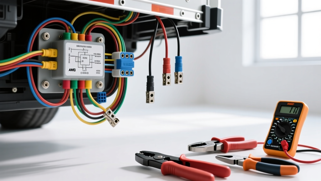
Introduction: The Economics of Trailer Brake Controller Installation
Installing an electric trailer brake controller is a critical safety upgrade for any tow vehicle. While many drivers defer to dealership service centers, analyzing a trailer brake controller wiring diagram reveals that the installation process is highly standardized. By understanding the exact tool requirements and material costs, DIY enthusiasts can save hundreds of dollars in labor fees while achieving a factory-grade, reliable electrical connection. This guide breaks down the financial and technical prerequisites for executing a 7-pin RV blade brake controller wiring diagram, ensuring you have the right equipment and budget before cutting into your vehicle's harness.
The Core Trailer Brake Controller Wiring Diagram (7-Pin Standard)
Before purchasing materials, you must understand the blueprint. The standard 7-way RV blade connector (SAE J286 compliant) is the foundation of modern electric brake systems. The brake controller primarily interacts with Pin 1 (Ground) and Pin 2 (Electric Brakes), while drawing auxiliary power from the battery via a dedicated heavy-gauge circuit.
| Pin | Function | Standard Wire Color | AWG Requirement |
|---|---|---|---|
| 1 | System Ground | White | 10 AWG |
| 2 | Electric Brakes (Controller Output) | Blue | 10 AWG |
| 3 | Tail / Running Lights | Brown | 16 AWG |
| 4 | 12V Auxiliary Power | Black | 10 AWG |
| 5 | Right Turn / Stop | Green | 16 AWG |
| 6 | Left Turn / Stop | Red | 16 AWG |
| 7 | Auxiliary / Reverse Lockout | Yellow | 16 AWG |
Note: Always verify vehicle-specific pinouts, as some older or European models may deviate from the SAE standard. For comprehensive vehicle-specific diagrams, consult etrailer's vehicle fit guide.
Essential Tool Checklist & Budget Breakdown
Executing a trailer brake controller wiring diagram properly requires more than a basic household toolkit. Automotive electrical systems are subject to extreme vibration, moisture, and thermal cycling. Using improper tools leads to high-resistance connections, voltage drop, and eventual brake failure. Below is the required tooling and estimated investment.
| Tool Category | Specific Tool Required | Purpose | Est. Cost |
|---|---|---|---|
| Wire Preparation | 10-12 AWG Self-Adjusting Strippers | Prevents nicking copper strands on heavy brake wires. | $25 - $40 |
| Crimping | Heavy-Duty Ratcheting Crimper | Ensures gas-tight, cold-weld connections on 10 AWG terminals. | $45 - $70 |
| Sealing | Adjustable Heat Gun (Dual Temp) | Shrinks adhesive-lined heat shrink to waterproof splices. | $30 - $50 |
| Testing | Digital Multimeter (DMM) | Verifies continuity, pinout accuracy, and voltage drop. | $25 - $60 |
| Routing | Flexible Fish Tapes & Loom | Routes 10 AWG wire through tight firewall grommets. | $15 - $25 |
Total Tool Investment: $140 - $245. If you already own a multimeter and basic strippers, your out-of-pocket tool cost drops significantly.
Material Costs: Wire, Breakers, and Connectors
The materials dictated by the wiring diagram must meet strict automotive standards. Never use household THHN wire; it lacks the chemical and heat resistance required for under-hood and under-chassis routing. You must use TXL (Thin-wall Cross-linked) or GXL automotive wire.
Bill of Materials (BOM) for a Standard Controller Install
- 10 AWG TXL Blue Wire (25 ft): $18.00 (Routes from controller to 7-pin receptacle).
- 10 AWG TXL Black Wire (15 ft): $12.00 (Routes from battery to controller power feed).
- 10 AWG TXL White Wire (10 ft): $8.00 (Controller and receptacle grounding).
- 30-Amp Auto-Reset Circuit Breaker: $14.00 (Mandatory for the 12V battery feed to prevent catastrophic shorts).
- 7-Way RV Socket & Harness Pigtail: $35.00 (Pre-wired with sealed weather-pack connectors).
- Adhesive-Lined Heat Shrink & Ring Terminals: $22.00 (1/4" and 5/16" stud sizes for battery and ground bolts).
- Corrugated Split Loom & Zip Ties: $15.00 (Protects undercarriage wiring from road debris).
Total Material Cost: ~$124.00. Compared to a dealership parts markup, sourcing high-quality TXL wire and OEM-recommended Tekonsha or Curt components ensures longevity at a fraction of the retail price.
Step-by-Step Execution: Applying the Tools to the Diagram
1. Power Feed and Circuit Protection
According to the diagram, the black 12V power wire must connect directly to the positive battery terminal. Crucial Step: Install the 30A auto-reset circuit breaker within 18 inches of the battery positive post. Strip the 10 AWG wire using your self-adjusting strippers, crimp a 5/16" ring terminal using the ratcheting crimper, and apply adhesive-lined heat shrink. Torque the battery terminal nut to the manufacturer's specification (typically 10-12 Nm) to prevent arcing.
2. Grounding Protocol
A poor ground is the number one cause of erratic trailer brake behavior. The white 10 AWG ground wire must terminate to a bare, unpainted metal surface on the vehicle chassis or directly to the negative battery terminal. Use a wire brush to remove paint and rust at the grounding point, apply a thin layer of dielectric grease after tightening, and seal the terminal with heat shrink.
3. Routing the Blue Brake Output Wire
The blue 10 AWG wire carries the pulsed DC voltage from the controller to Pin 2 on the 7-way connector. Route this wire through the vehicle's existing firewall grommet using a fish tape. Never pierce a factory grommet directly; use a pick tool to slide past existing harnesses, or drill a new hole and install a rubber firewall pass-through grommet to prevent sheet metal from slicing the wire insulation.
DIY vs. Professional Installation: ROI Analysis
Is executing the trailer brake controller wiring diagram yourself financially sound? Let us compare the costs.
| Installation Method | Parts Cost | Labor Cost | Total Estimate | Warranty |
|---|---|---|---|---|
| Dealership / Pro Installer | $250 - $350 (Marked up) | $150 - $250 (1.5 - 2 hrs) | $400 - $600 | 1 Year / 12k Miles |
| DIY (Using This Guide) | $124 (High-grade TXL) | $0 (3-4 hrs your time) | $124 | Lifetime (Your own work) |
The Verdict: The ROI on DIY installation is immediate, saving upwards of $350. Furthermore, by using ratcheting crimpers and adhesive heat shrink, a DIY install often exceeds the quality of a rushed dealership install that may rely on basic crimp caps or electrical tape.
Common Failure Modes & Troubleshooting Costs
Even with a perfect diagram, environmental factors can degrade connections. When troubleshooting, your $30 Digital Multimeter becomes your most valuable asset.
- Symptom: Brakes lock up randomly or controller displays 'SH' (Short).
- Cause: The blue brake wire has chafed against the exhaust or frame, grounding out.
- Fix Cost: $5 for split loom and electrical tape. Use the DMM in continuity mode to trace the short.
- Symptom: Controller powers on, but no output to trailer brakes.
- Cause: Voltage drop across a corroded white ground wire or a blown 30A inline breaker.
- Fix Cost: $2 for a new ring terminal and sandpaper. Measure voltage drop across the ground circuit; it should read less than 0.1V under load.
Conclusion
Mastering a trailer brake controller wiring diagram is less about electrical engineering and more about meticulous preparation and material selection. By investing roughly $125 in high-quality TXL wire, auto-reset breakers, and proper ratcheting crimpers, you secure a towing setup that is safer, more reliable, and significantly cheaper than professional alternatives. Always adhere to SAE standards, respect wire gauge requirements, and never compromise on your grounding points.