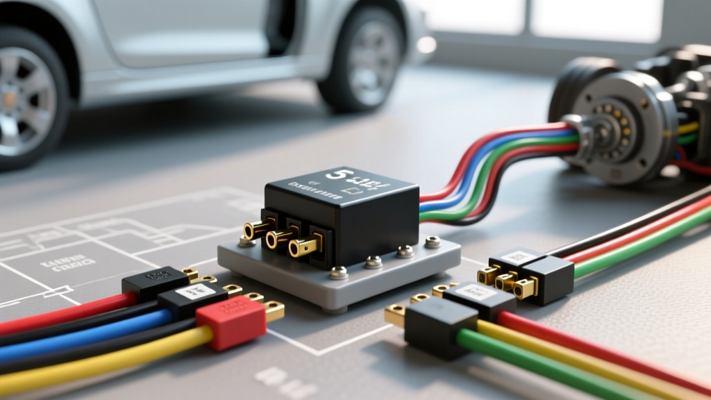
The Problem: Factory Reverse Light Circuits and Surge Brakes
Upgrading a tow vehicle to handle a surge brake trailer with a reverse lockout solenoid is a common modification project. Trailers equipped with surge brakes (such as those using the Titan Model 60 or Dexter DX7.6 actuators) require a 12V signal to disengage the brakes when the tow vehicle is placed in reverse. This signal is typically routed through the blue wire on a 5-way flat connector. However, modern trucks and SUVs utilize complex Body Control Modules (BCMs) and multiplexed wiring harnesses to manage exterior lighting.
Factory reverse light circuits are generally protected by 10A or 15A fuses and are designed only to power low-draw LED backup lamps or incandescent bulbs. A hydraulic reverse lockout solenoid experiences a massive inrush current—often between 10 and 15 amps—upon initial engagement. Connecting this solenoid directly to the factory reverse light circuit will inevitably cause severe voltage drop, trigger BCM fault codes, or blow the vehicle's reverse lighting fuse, leaving you locked out of reverse or stranded with a trailer that refuses to roll backward. The definitive solution for this upgrade project is integrating a heavy-duty 5 pin car relay to bypass the factory wiring and pull power directly from the battery.
Why Use a 5 Pin Car Relay for Trailer Wiring Upgrades?
While a standard 4-pin relay (SPST - Single Pole Single Throw) can handle the basic switching of high current, a 5 pin car relay (SPDT - Single Pole Double Throw) offers a distinct advantage for custom modification projects. The fifth terminal (87a) provides a 'Normally Closed' circuit. In this specific trailer wiring upgrade, we will use the 87a terminal to wire a dashboard indicator LED. This LED will illuminate whenever the vehicle is not in reverse, providing a visual confirmation that the surge brakes are active and the lockout solenoid is disengaged. This prevents the accidental towing of a trailer with locked brakes, which can cause catastrophic overheating and hub failure.
5-Pin Bosch Relay Pinout and Terminal Identification
For this project, we recommend using a high-quality, IP67-rated waterproof Bosch-style mini ISO relay rated for at least 30A continuous / 40A peak. Below is the standard DIN 72552 terminal identification for the 5 pin car relay:
| Terminal Pin | Designation | Function in Lockout Circuit | Recommended Wire Gauge |
|---|---|---|---|
| 30 | Common (COM) | Main 12V+ Power Input from Battery | 10 AWG (Red) |
| 87 | Normally Open (NO) | 12V+ Output to 5-Way Flat Blue Pin | 10 AWG (Blue) |
| 87a | Normally Closed (NC) | Output to Dashboard Indicator LED | 18 AWG (Green) |
| 86 | Coil Positive (+) | Trigger Signal from Factory Reverse Light | 16 AWG (White) |
| 85 | Coil Negative (-) | Chassis Ground | 16 AWG (Black) |
Required Materials and SAE Wiring Standards
Before beginning the modification, ensure you are using automotive-grade materials. According to SAE J1128 standards, under-hood wiring must utilize cross-linked polyethylene (XLPE) insulation, such as GXL or TXL wire, to withstand high engine bay temperatures. Standard PVC wire will melt and cause short circuits.
- 1x IP67 Waterproof 5-Pin 12V Relay (40A) with matching pigtail harness
- 1x 20A Inline ATC Fuse Holder with 20A Blade Fuse
- 10 AWG GXL Red Wire (Battery to Relay)
- 10 AWG GXL Blue Wire (Relay to 5-Way Connector)
- 16 AWG GXL Wire (White, Black, and Green for trigger/ground/LED)
- Adhesive-lined heat shrink butt connectors and ring terminals
- 1x 5mm Dashboard LED (12V) with built-in resistor
Step-by-Step Reverse Lockout Relay Upgrade Project
Step 1: Route the Primary High-Current Power
Disconnect the negative battery terminal. Run the 10 AWG red wire from the positive battery post to your chosen relay mounting location in the engine bay. Install the 20A inline ATC fuse holder within 6 inches of the battery terminal. Crimp a 5/16-inch ring terminal onto the battery end, securing it with a torque of 10-12 Nm to ensure a low-resistance connection. Crimp the relay-side end to the Pin 30 wire on the relay pigtail using an adhesive-lined heat shrink butt connector. Apply heat until the adhesive seals the wire strands.
Step 2: Tap the Factory Reverse Light Trigger
Locate the factory reverse light wire at the driver's side rear taillight assembly (typically light green or purple, depending on the manufacturer). Use a posi-tap or solder-and-heat-shrink method to connect a 16 AWG white wire. Route this wire along the frame rail to the front engine bay. Connect this white trigger wire to Pin 86 on the relay pigtail. This ensures the relay coil is only energized when the transmission is in reverse.
Step 3: Establish a Clean Chassis Ground
Locate a bare metal bolt on the engine block or inner fender well near the relay. Sand away any paint or corrosion to expose bare steel. Attach a 16 AWG black wire with a ring terminal to this ground point. Connect the other end to Pin 85 on the relay. A poor ground is the number one cause of relay chatter and solenoid failure. For BCM-protected vehicles, it is highly recommended to solder a 1N4001 flyback diode across Pins 85 and 86 (cathode to 86, anode to 85) to prevent inductive voltage spikes from damaging the truck's computer when the relay coil de-energizes.
Step 4: Wire the Output to the 5-Way Flat Connector
Connect a 10 AWG blue wire to Pin 87 (Normally Open). Route this wire to the rear of the vehicle. If you are upgrading from a 4-way flat to a 5-way flat, cut off the old connector and install a new 5-way flat plug (e.g., Hopkins 48035). Solder the 10 AWG blue wire directly to the Blue terminal on the 5-way connector. When the truck is shifted into reverse, Pin 86 receives 12V, energizing the coil, which pulls the internal contact from 87a to 87, sending full battery current to the trailer's lockout solenoid.
Step 5: The 87a Dashboard Indicator Modification
To utilize the 5th pin, connect an 18 AWG green wire to Pin 87a. Route this wire through the firewall into the cabin. Connect it to the positive leg of a 12V dashboard LED, and ground the LED's negative leg to the dash frame. When the truck is in Park or Drive, power flows from Pin 30 to Pin 87a, illuminating the LED to warn you that the surge brakes are currently active and locking out reverse. When you shift into Reverse, the LED turns off, confirming the solenoid has engaged and the trailer is free to roll backward.
Troubleshooting Common Relay Failure Modes
Even with a flawless installation, environmental factors and trailer wiring faults can cause issues. Use this diagnostic matrix to troubleshoot the 5 pin car relay circuit:
- Symptom: Relay clicks rapidly (chatters) when shifted into reverse.
Cause: Voltage drop on the trigger circuit or a weak ground on Pin 85. The factory reverse wire cannot supply the 150mA needed to hold the coil closed.
Fix: Check for corrosion on the taillight ground. Add a secondary ground wire from the taillight housing directly to the chassis. - Symptom: Fuse blows immediately upon shifting into reverse.
Cause: Short circuit in the 10 AWG blue wire between Pin 87 and the 5-way connector, or a seized trailer lockout solenoid drawing excessive amperage.
Fix: Disconnect the trailer. Test the resistance of the solenoid with a multimeter (should read 1.0 to 1.5 ohms). Inspect the 5-way plug for bent pins or moisture ingress causing a short between the blue and white (ground) pins. - Symptom: Solenoid hums but brakes remain locked in reverse.
Cause: Insufficient amperage reaching the solenoid, often due to undersized wire on the trailer side.
Fix: Verify the trailer's internal wiring to the actuator is at least 12 AWG. Many cheap trailers use 16 AWG wire for the lockout, which starves the solenoid of the current required to fully retract the hydraulic bypass valve.
Final Verification and Safety Checks
After completing the wiring, reconnect the battery. With the trailer disconnected, use a digital multimeter to probe the blue pin on the truck's 5-way flat connector. In Park, you should read 0V. Shift into Reverse (with the parking brake firmly applied and wheels chocked); you should read a minimum of 12.2V at the connector pin. This confirms that the 5 pin car relay is successfully bypassing the factory BCM limitations and delivering the robust, high-amperage current required for reliable surge brake lockout operation. For comprehensive trailer connector standards and pinout diagrams, always refer to the etrailer 5-way wiring guide and your vehicle's specific OEM service manual.