The Engineering Case for a Centralized Junction Box
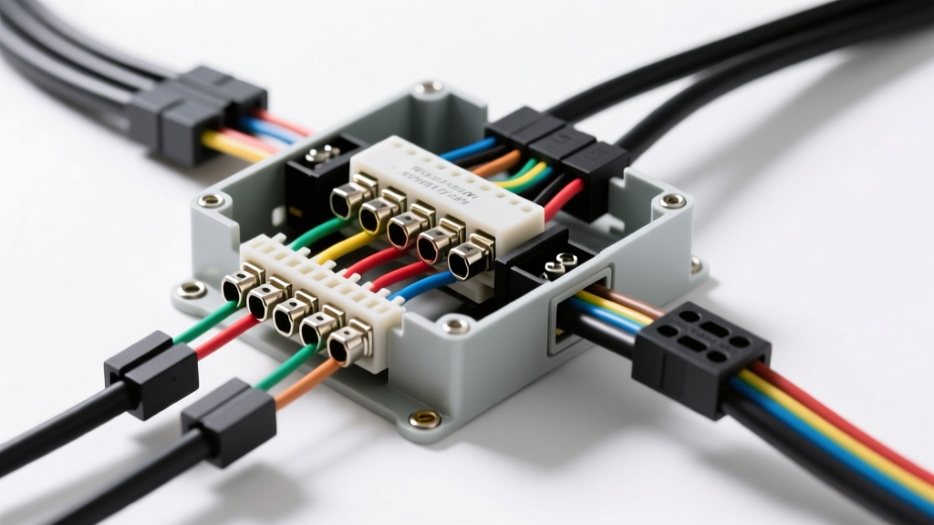
When fabricating or restoring a heavy-duty utility trailer, horse trailer, or fifth-wheel RV, relying on inline butt connectors and electrical tape is a guaranteed path to electrical failure. The harsh environment underneath a trailer exposes wiring to road spray, debris impact, and extreme thermal cycling. By utilizing a centralized, IP67-rated enclosure, you transform a chaotic web of splices into a structured, easily diagnosable node. A proper trailer wiring junction box diagram serves as the master blueprint for this node, ensuring that high-current circuits like electric brakes and auxiliary charging are isolated from low-current lighting circuits, thereby mitigating electromagnetic interference and voltage drop.
Furthermore, copper wire is highly susceptible to capillary action. If an inline splice fails and exposes bare copper to moisture, water will wick its way up the wire strands under the insulation, corroding the harness all the way to the tow vehicle. A sealed junction box with integrated cable glands and adhesive-lined terminations halts this capillary action, protecting the integrity of the entire trailer harness.
Anatomy of a Heavy-Duty Trailer Junction Box
Before mapping the circuits, it is critical to select the correct hardware. An automotive-grade junction box should feature a UV-stabilized polycarbonate or die-cast aluminum housing. Inside, the terminal block must utilize nickel-plated brass screws and copper bus bars. Steel screws will rapidly corrode when subjected to the galvanic reaction caused by copper ring terminals and road salt.
- Enclosure Rating: Minimum IP65 (dust tight and protected against water jets); IP67 preferred for low-clearance trailers.
- Terminal Block: 12-position or 14-position barrier strip with 3/8-inch pitch.
- Cable Glands: Nylon PG11 and PG9 glands with neoprene seals to clamp the outer jacket of the main 7-way umbilical, providing strain relief.
The Core Trailer Wiring Junction Box Diagram (7-Way RV Blade)
The following mapping aligns with the RV Industry Association (RVIA) color codes for 7-way RV blade connectors. While older agricultural or commercial trailers may use different color schemes, the RVIA standard is the benchmark for modern recreational and heavy-duty utility trailers.
| 7-Way Pin | Function | RVIA Wire Color | Recommended AWG | Terminal Torque Spec |
|---|---|---|---|---|
| Pin 1 (Top) | Ground Return | White | 8 AWG | 1.2 Nm (10 in-lbs) |
| Pin 2 | Left Turn / Stop | Red | 12 AWG | 0.8 Nm (7 in-lbs) |
| Pin 3 | Tail / Running Lights | Brown | 12 AWG | 0.8 Nm (7 in-lbs) |
| Pin 4 | Right Turn / Stop | Green | 12 AWG | 0.8 Nm (7 in-lbs) |
| Pin 5 | Electric Brakes | Blue | 10 AWG | 1.0 Nm (9 in-lbs) |
| Pin 6 | 12V Aux / Battery Charge | Black | 10 AWG (or 8 AWG) | 1.2 Nm (10 in-lbs) |
| Pin 7 | Reverse / Aux | Yellow | 12 AWG | 0.8 Nm (7 in-lbs) |
High-Current Circuit Routing: Electric Brakes & Auxiliary Power
The most common failure point in DIY trailer wiring is undersizing the Blue (Brakes) and Black (Auxiliary) circuits. According to SAE J1128 standards for low-tension primary cable, wire gauge must be selected based on the total length of the circuit run, not just the amperage draw at the source. A dual-axle trailer with four 10-inch electric brake assemblies can draw up to 16 amps under heavy braking conditions.
If you route 12 AWG wire over a 25-foot run from the junction box to the axles, the resistance will cause a significant voltage drop. The tow vehicle's brake controller may output 12V, but the brake magnets will only see 9V, resulting in weak braking performance and overheated wiring. By mandating 10 AWG wire for the Blue circuit from the 7-way plug, through the junction box, and out to the axle hubs, you minimize resistance and ensure maximum magnetic clamping force.
Breakaway Switch and Battery Charging Integration
The junction box is the ideal location to integrate the breakaway switch and the trailer's onboard battery bank. The Black (12V Aux) wire from the 7-way should terminate on a bus bar linked to a 30A auto-reset circuit breaker, which then feeds the trailer battery positive. The breakaway switch pin must be wired directly to the trailer battery positive via a separate 10 AWG jumper inside the junction box. This ensures that if the trailer detaches and the breakaway pin is pulled, the brakes receive full battery voltage without backfeeding through the 7-way umbilical, which could otherwise fry the tow vehicle's brake controller module.
Advanced Termination and Environmental Sealing
As detailed in Tekonsha's OEM installation guides, the physical termination of the wire to the terminal block is just as critical as the wire gauge. Never use solder on high-vibration trailer circuits. Solder creates a rigid joint that will work-harden and snap under the constant harmonic vibration of highway towing. Instead, use a ratcheting crimper to affix #10 vinyl-insulated or heat-shrink ring terminals.
For environmental sealing, strip the wire, crimp the terminal, and apply 3M FP-301 adhesive-lined heat shrink. When heated, the inner thermoplastic lining melts and flows around the wire strands, creating a watertight seal that prevents oxygen and moisture from reaching the copper. Before tightening the brass screws on the terminal block, apply a small dab of dielectric grease to the threads to prevent galvanic corrosion and seizing.
Diagnostic Troubleshooting Matrix
When electrical gremlins arise, the junction box is your primary diagnostic node. By isolating the trailer harness from the tow vehicle, you can use a multimeter to determine if the fault lies in the truck or the trailer. Below is a matrix of common symptoms and their junction-box-specific failure modes.
| Symptom | J-Box Failure Mode | Corrective Action |
|---|---|---|
| Brake controller reads 'SH' (Short) | Stray copper strand from Blue wire bridging to White ground terminal. | Trim wire back, re-crimp ring terminal, apply heat shrink. |
| Running lights dim when brakes applied | Shared ground path overload; White wire undersized or loose at J-box. | Upgrade White ground to 8 AWG; add secondary chassis ground. |
| Left turn signal flashes rapidly | Corrosion on Red terminal block screw causing high resistance. | Clean brass contact with wire brush, apply dielectric grease, re-torque. |
| Trailer battery drains while parked | Parasitic draw from 12V accessories backfeeding through Black terminal. | Install a 120A continuous duty solenoid relay controlled by the ignition circuit. |
Final Validation and Testing
Once all terminations are complete and the junction box lid is sealed, perform a continuity and load test. Use a digital multimeter to verify that the resistance between the 7-way ground pin and the trailer chassis is less than 0.2 ohms. Next, apply a 12V load tester directly to the junction box terminals to simulate the tow vehicle's output. This advanced methodology ensures your trailer wiring junction box diagram translates into a robust, fail-safe electrical system capable of withstanding thousands of miles of heavy-duty towing.