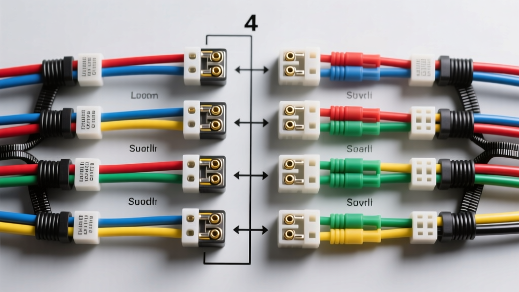
Project Overview: Upgrading to a Custom 4-Wire Harness
Upgrading a vintage utility trailer or modifying a custom-built flatbed requires a complete departure from the cheap, pre-packaged 18 AWG PVC wiring kits found at big-box stores. When you are dealing with high-vibration environments, exposure to road debris, and the electrical demands of modern tow vehicles, referencing a precise 4 wire trailer wiring diagram left and right layout is the foundational step for a reliable lighting system. This modification project focuses on stripping out degraded incandescent circuits and installing a robust, SAE-compliant 4-way flat harness optimized for LED lighting. By correctly separating and routing the left and right turn/brake signal circuits, you eliminate the most common failure points in trailer electrics: voltage drop, ground backfeed, and hyperflashing.
Understanding the 4 Wire Trailer Wiring Diagram Left and Right
The standard 4-pin flat connector (often referred to as a 4-way flat) operates on a combined stop/turn signal system. Unlike European 7-pin setups that separate brake and turn signals, the North American 4-wire system merges these functions. Pin 3 handles the left turn and left brake, while Pin 4 handles the right turn and right brake. When planning a custom lighting harness, understanding how to split these circuits at the trailer tongue and route them down the respective frame rails is critical. If the left and right circuits are crossed, or if they share a compromised ground path, the tow vehicle's Body Control Module (BCM) will detect a short and shut down the trailer lighting circuit entirely.
SAE-Compliant Pinout and Wire Specifications
For this upgrade, we are abandoning standard PVC wire in favor of SAE J1128 GXL (cross-linked polyethylene) automotive wire. GXL wire features a thinner, tougher insulation that resists engine bay heat, UV degradation, and abrasion from road debris. Below is the specification chart for the custom 4-wire build.
| Pin Position | Circuit Function | Standard Color Code | Recommended GXL AWG | Max Amperage Load |
|---|---|---|---|---|
| 1 (Ground) | Chassis / Circuit Ground | White | 14 AWG | 15A |
| 2 (Tail) | Tail, Running, and Marker Lights | Brown | 16 AWG | 7.5A |
| 3 (Left) | Left Turn Signal & Stop Lamp | Yellow | 16 AWG | 10A |
| 4 (Right) | Right Turn Signal & Stop Lamp | Green | 16 AWG | 10A |
Modification Phase 1: Routing and Splitting the Harness
The most vulnerable point in any 4 wire trailer wiring diagram left and right configuration is the junction where the main trunk line splits to feed the left and right taillights. Pre-made kits use cheap T-connectors that easily corrode. For this modification, we will use a marine-grade, adhesive-lined heat shrink T-splice.
- Tongue Routing: Run the 4-wire bundled loom through the trailer tongue. Use a rubber grommet where the wire exits the metal to prevent the sharp steel edge from slicing the GXL insulation over time.
- The Split Point: Measure exactly 36 inches behind the coupler. Strip the outer jacket and separate the Yellow (Left) and Green (Right) wires from the Brown and White wires.
- Adhesive T-Splicing: Crimp the Yellow and Green wires into a sealed T-connector using a ratcheting open-barrel crimper. Apply heat until the adhesive sealant purges from the ends of the heat shrink tube. This creates a 100% waterproof junction.
- Frame Routing: Route the Yellow wire down the left (driver's side) frame rail and the Green wire down the right (passenger side) frame rail. Secure the wires every 18 inches using UV-resistant zip ties and split loom conduit. Never route trailer wiring near exhaust components or moving suspension parts.
Modification Phase 2: LED Integration and Load Resistors
Upgrading from incandescent bulbs to LED pods drastically reduces amperage draw, which is excellent for reducing voltage drop. However, modern tow vehicles utilize pulse-width modulation (PWM) and BCMs that monitor circuit resistance. If the BCM detects the low resistance of LED lights on the Yellow and Green circuits, it will assume a bulb is out and trigger a hyperflash or cut power to the circuit.
Wiring 6-Ohm Load Resistors
To trick the BCM into thinking incandescent bulbs are still installed, you must wire load resistors in parallel on the left and right turn/brake circuits. For this project, use 6-Ohm, 50-Watt aluminum-housed resistors.
- Placement: Mount the resistor on the left frame rail, splicing it between the Yellow (16 AWG) wire and the White (14 AWG) ground wire, approximately 12 inches before the left LED pod.
- Thermal Management: Load resistors generate extreme heat—up to 300°F under heavy braking. You must bolt the aluminum housing directly to the bare steel trailer frame using star washers and stainless steel hardware to act as a heatsink. Never mount a load resistor near plastic conduit, zip ties, or the trailer floor wood.
- Repeat for Right Side: Install the second resistor on the Green wire and White ground wire on the right frame rail.
Advanced Grounding Protocols for Custom Builds
According to data from etrailer's technical troubleshooting archives, over 80% of trailer lighting failures are ground-related. In a standard 4-wire setup, the white ground wire is often ring-terminated to the trailer tongue, relying on the trailer frame to carry the ground current back to the taillights. This fails when trailer hinges, rust, or wooden beds break the electrical continuity.
The Expert Fix: Do not rely on the trailer frame for grounding. Run a dedicated 14 AWG White GXL wire all the way from the 4-pin connector, down the left frame rail alongside the Yellow wire, and directly to the negative terminal of the left LED pod. Run a second 14 AWG White wire down the right side for the right LED pod and marker lights. This creates a dedicated, isolated ground circuit back to the tow vehicle's battery negative, completely eliminating frame-induced voltage drop.
Troubleshooting Left/Right Crossover and Backfeed
During the initial testing phase of your custom 4-wire modification, you may encounter crossover issues. Here is a diagnostic decision tree for the most common left/right signal anomalies:
- Symptom: Activating the left turn signal causes both left and right trailer lights to flash dimly.
- Cause: Ground backfeed. The left taillight is seeking a ground through the right taillight's circuit because the dedicated ground wire is compromised.
- Fix: Check the ring terminal connection at the left LED pod. Ensure you have scraped away all powder coat, paint, and rust to achieve bare metal-to-metal contact before applying dielectric grease and tightening the bolt.
- Symptom: Pressing the brake pedal causes the trailer running lights (Brown circuit) to illuminate brightly, and the turn signals lock out.
- Cause: A short between the Green/Yellow circuits and the Brown circuit, usually caused by a pinched wire where the harness passes through a metal bracket.
- Fix: Inspect the split loom conduit at the tongue and axle crossings. Use a digital multimeter in continuity mode to test for shorts between Pin 2 (Brown) and Pin 3 (Yellow) at the 4-way flat connector.
Final Validation and Authority Sources
Before taking the modified trailer on the highway, perform a comprehensive voltage drop test. With the tow vehicle running and the trailer connected, use a multimeter to measure the voltage at the 4-pin connector, and then measure it directly at the left and right LED pods while the brake pedal is depressed. A healthy 4 wire trailer wiring diagram left and right custom harness built with 14/16 AWG GXL wire should exhibit a voltage drop of no more than 0.3V across the entire length of the trailer. For further reading on commercial and heavy-duty trailer lighting standards, refer to the SAE J558 Trailer Lighting Standards documentation, which outlines the exact photometric and electrical requirements for all aftermarket trailer lighting modifications.