Pre-Installation Prep & Required Tools
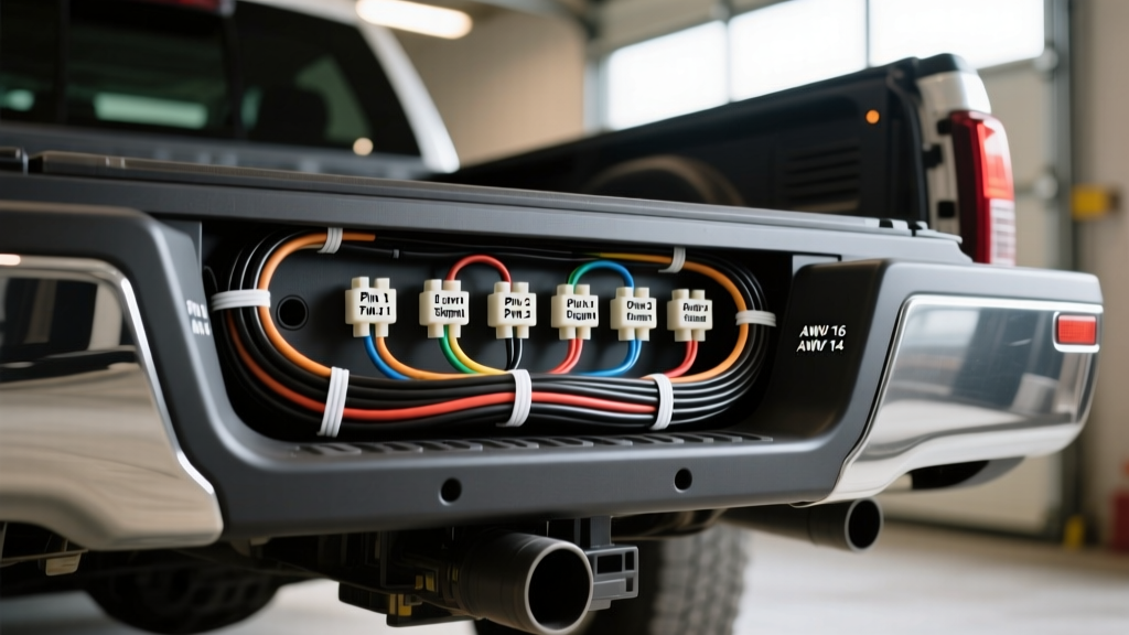
Upgrading your Ford F-150 from a standard 4-way flat to a heavy-duty 7-pin trailer wiring harness is essential for towing campers, horse trailers, or any rig equipped with electric brakes. While modern F-150s feature pre-routed towing packages, installing the physical harness and integrating an aftermarket proportional brake controller requires precision, correct wire gauging, and adherence to SAE J560 standards. This practical guide covers the complete installation of an OEM-style 7-way RV blade receptacle and the routing of 10 AWG auxiliary and brake circuits.
Required Tools and Materials
- 7-Pin RV Blade Socket with Prewired Harness (OEM or Curt/Tekonsha equivalent)
- 10 AWG Primary Wire (Blue for brakes, Black for 12V aux, White for ground)
- Adhesive-lined marine-grade heat shrink butt connectors (14-16 AWG and 10-12 AWG)
- Wire loom split tubing and UV-resistant zip ties
- Dielectric silicone grease
- Digital Multimeter (DMM)
- Heat gun and heavy-duty wire strippers
7-Pin RV Blade Connector Pinout & Wire Specifications
Before splicing any circuits, you must understand the standardized SAE J560 pinout for the 7-way connector. Mismatching wire colors or using undersized gauges will result in voltage drop, erratic brake controller behavior, or melted connectors. Always verify pin positions by looking at the back (wiring side) of the socket.
| Pin Number | Function | Standard Wire Color | Minimum AWG Size | Circuit Protection |
|---|---|---|---|---|
| 1 (Ground) | Chassis Ground | White | 10 AWG | Direct to Frame |
| 2 (Brakes) | Electric Trailer Brakes | Blue | 10 AWG | 30A Auto-Reset Breaker |
| 3 (Tail) | Tail / Running Lights | Brown | 14 AWG | 15A Fuse |
| 4 (Aux) | 12V Auxiliary Power | Black | 10 AWG | 40A Maxi Fuse |
| 5 (Right) | Right Turn / Stop | Green | 14 AWG | 15A Fuse |
| 6 (Left) | Left Turn / Stop | Yellow | 14 AWG | 15A Fuse |
| 7 (Reverse) | Reverse Lights / Aux | Purple | 14 AWG | 15A Fuse |
Step-by-Step Installation: Upgrading to the 7-Pin Harness
Step 1: Disconnecting the Battery & Locating the OEM Connector
Begin by disconnecting the negative terminal on your F-150's battery to prevent shorting the BCM (Body Control Module) lighting circuits. Locate the OEM 4-pin flat connector under the rear bumper, typically tucked behind the driver-side frame rail or near the spare tire. Many Ford towing packages include a blunt-cut 7-pin jumper harness in the glovebox. If your truck has the factory tow package, you will find a square 8-pin OEM connector plugged into a dummy cap on the frame rail. Simply uncap it and plug in the 7-way socket adapter.
Note: If your F-150 lacks the factory tow package, you must splice the 14 AWG lighting circuits (Brown, Green, Yellow) into the rear tail light harness using T-taps or, preferably, by stripping back the loom and soldering/heat-shrinking directly to the factory wires.
Step 2: Routing the Heavy-Gauge Power and Brake Wires
The most critical failure point in any trailer wiring harness is the 10 AWG power and brake circuits. These wires carry high amperage and are susceptible to voltage drop if routed improperly.
- Run the Blue (Brake) and Black (12V Aux) wires from the rear 7-pin socket along the driver-side frame rail to the engine bay.
- Maintain a minimum 6-inch clearance from the exhaust system to prevent the wire insulation from melting. Use split wire loom and secure the bundle every 12 inches with UV-resistant zip ties.
- Terminate the Black 12V wire at the under-hood fuse box or directly to the positive battery terminal via a 40A Maxi fuse holder. This circuit powers the trailer's interior lights, battery charging, and slide-outs.
- Terminate the Blue Brake wire to the output terminal of your aftermarket brake controller (located under the dash) or to the factory ITBC (Integrated Trailer Brake Controller) blue output wire.
Step 3: Grounding and Weatherproofing
A poor ground causes 80% of all trailer lighting issues. Do not simply wrap the White 10 AWG ground wire around a rusty bolt. Sand the frame rail down to bare, shiny metal using 80-grit sandpaper. Attach a heavy-duty ring terminal, secure it with a self-tapping hex-head screw or an existing chassis bolt, and coat the connection heavily in dielectric silicone grease to prevent galvanic corrosion. Apply the same grease to the internal pins of the 7-way socket to repel moisture and road salt.
Integrating the Aftermarket Brake Controller
If your F-150 does not have the factory ITBC, you will likely install an aftermarket proportional controller like the Tekonsha Prodigy P3. Ford pre-wires the brake controller blunt-cut wires under the steering column, usually tucked behind a removable lower dash panel. According to the Ford Towing Guide, the standard Ford upfitter brake controller pigtail features four wires:
- Red/Black Stripe: 12V Power (Connect to Brake Controller Red wire via 30A breaker)
- White: Ground (Connect to Brake Controller White wire)
- Blue: Output to Trailer Brakes (Connect to Brake Controller Blue wire, routes to rear 7-pin)
- Purple/White or Light Blue: Stoplight Switch Input (Connect to Brake Controller Red wire)
Use adhesive-lined heat shrink for all under-dash connections. The heat-activated sealant prevents copper oxidation and ensures the connection withstands the vibration of the steering column.
Troubleshooting Common Harness Failures
After reconnecting the battery, use a Digital Multimeter (DMM) to verify the harness before plugging in the trailer. Refer to this decision tree for common installation faults:
- Symptom: Trailer running lights flicker or dim when brakes are applied.
Cause: Voltage drop on the ground circuit. The 14 AWG tail light ground cannot handle the combined amperage of the running lights and brake lights.
Fix: Upgrade the ground wire at the 7-pin socket to 10 AWG and ensure the frame grounding point is bare metal. - Symptom: Brake controller reads 'No Trailer Connected' despite a plugged-in 7-pin.
Cause: The Blue brake wire is severed, or the controller is not receiving the stoplight signal.
Fix: Probe the Purple/White stoplight wire under the dash with a DMM while a helper presses the brake pedal. You should see 12V. If 0V, check the BCM stoplight fuse. - Symptom: 12V Auxiliary pin (Pin 4) has no power.
Cause: Many modern Ford F-150s utilize a Tow/Haul relay that only activates the 12V aux pin when the ignition is ON and the transmission is in Tow/Haul mode.
Fix: Verify ignition state. If still dead, check the 40A Maxi fuse in the under-hood BJB (Battery Junction Box).
Authoritative References
For comprehensive electrical standards and vehicle-specific towing limitations, always consult the following resources:
- SAE International J560 - Standard for 7-Way Heavy Duty Electrical Connectors.
- Ford Motor Company Official Towing & Trailering Guide - Upfitter wiring and ITBC integration specs.
- etrailer.com Wiring FAQ - Practical application guides for aftermarket harness routing and brake controller pinouts.