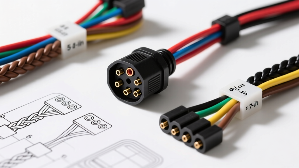
Understanding Car Trailer Plug Wiring Standards
When addressing car trailer plug wiring, technicians and DIYers must adhere to standardized color codes and pinouts established by the Society of Automotive Engineers (SAE) and the Federal Motor Carrier Safety Administration (FMCSA). Whether you are wiring a simple 4-pin flat connector for a lightweight utility trailer or a 7-pin RV blade for a travel trailer equipped with electric brakes, understanding the underlying electrical architecture is critical. Improper wiring leads to harness meltdowns, vehicle CAN-bus faults, and catastrophic brake controller failures.
This complete walkthrough dissects the pinouts, wire gauge (AWG) requirements, and real-world failure modes for the most common trailer connectors used in North America. For official regulatory lighting requirements, refer to FMCSA 49 CFR § 393.9 and the SAE J286 Standard for trailer connector pinouts.
The 4-Pin Flat Connector: Basic Lighting Circuits
The 4-pin flat connector is the universal standard for light-duty car trailer plug wiring, supporting trailers under 3,000 lbs GVWR without electric brakes. It multiplexes the brake and turn signal circuits onto a single filament (or LED driver) per side.
4-Pin Pinout and Color Code
| Pin Position | Function | Standard Wire Color | Recommended AWG |
|---|---|---|---|
| Pin 1 (Leftmost) | Ground (Chassis) | White | 14 AWG (12 AWG preferred) |
| Pin 2 | Tail / Running Lights | Brown | 16 AWG |
| Pin 3 | Left Turn / Stop | Yellow | 16 AWG |
| Pin 4 (Rightmost) | Right Turn / Stop | Green | 16 AWG |
Expert Insight: While 16 AWG is standard for lighting circuits, upgrading the white ground wire to 12 AWG is highly recommended. LED trailer lights draw significantly less current than incandescent bulbs, which means they cannot "bridge" poor mechanical grounds through the hitch ball. A dedicated, heavy-gauge white wire bolted to a clean, bare-metal point on the vehicle chassis and the trailer tongue is mandatory for reliable operation.
The 5-Pin Flat Connector: Surge Brake Lockout
The 5-pin flat connector builds upon the 4-pin layout by adding a fifth circuit, primarily used on boat trailers and heavy utility trailers equipped with hydraulic surge brakes.
- Pin 5 (Center/Blue): Reverse Light Circuit / Surge Brake Solenoid Lockout.
When the tow vehicle is shifted into reverse, the 12V signal from the reverse light circuit travels through the blue wire to a solenoid on the trailer's surge brake coupler. This solenoid physically blocks hydraulic fluid from engaging the trailer brakes while backing up. If your car trailer plug wiring lacks this 5th pin, you will experience severe brake drag and tire lockup when reversing.
The 7-Pin RV Blade: Heavy-Duty Towing & Electric Brakes
For travel trailers, horse trailers, and car haulers exceeding 3,000 lbs, the 7-pin RV blade (SAE J286) is the undisputed standard. It separates the brake and turn signals on the vehicle side (requiring a 3-to-2 wire converter on the trailer) and adds circuits for electric brakes and 12V auxiliary power.
7-Pin RV Blade Pinout (Vehicle Side / Female Receptacle)
Note: Pin numbering is standardized looking at the vehicle-side female receptacle.
| Pin | Clock Position | Function | Wire Color | AWG Spec |
|---|---|---|---|---|
| 1 | 7:00 | Ground (Chassis) | White | 8 AWG |
| 2 | 5:00 | Electric Brakes Output | Blue | 10 AWG |
| 3 | 9:00 | Tail / Marker Lights | Brown | 14 AWG |
| 4 | 11:00 | Left Turn / Stop | Yellow | 14 AWG |
| 5 | Center | 12V Auxiliary Power | Black | 10 AWG |
| 6 | 1:00 | Right Turn / Stop | Green | 14 AWG |
| 7 | 3:00 | Reverse / Backup Lights | Purple | 14 AWG |
Wire Gauge (AWG) and Circuit Protection Specifications
Using undersized wire in car trailer plug wiring causes severe voltage drop, leading to dim lights, slow brake solenoid engagement, and overheated harnesses. The following chart dictates the minimum copper wire gauge based on standard circuit amperages.
| Circuit Type | Max Continuous Amperage | Minimum AWG (Up to 25ft) | Fuse / Breaker Rating |
|---|---|---|---|
| Main Ground (White) | 40A+ | 8 AWG | N/A (Direct to Chassis) |
| Electric Brakes (Blue) | 15A (per axle pair) | 10 AWG | 30A Auto-Reset Breaker |
| 12V Aux / Charge (Black) | 30A | 10 AWG | 40A Maxi Fuse |
| Lighting Circuits | 10A | 14 AWG | 15A Mini Fuse |
Modern Vehicle Integration: CAN-Bus, PWM, and Converters
Modern vehicles (2015 and newer) rarely output raw 12V DC to the trailer plug. Instead, they use Pulse Width Modulation (PWM) and multiplexed CAN-bus signals to monitor bulb health and reduce wiring weight. If you plug a standard LED trailer directly into a modern SUV without the proper tow module, the vehicle's Body Control Module (BCM) will detect an "open circuit" (due to the low draw of LEDs) and trigger a dashboard error, hyper-flashing, or completely shut off the circuit.
Solving the PWM Issue
When performing car trailer plug wiring on modern crossovers and trucks, you must use a powered tail light converter. This device taps into the vehicle's lighting signals using high-impedance sensors (drawing near-zero current) and triggers an internal relay powered directly by the vehicle's battery. This isolates the trailer's electrical load from the vehicle's sensitive BCM.
Warning: Never use a standard incandescent test light to probe modern trailer wiring harnesses. The low resistance of the test light can trigger the BCM's short-circuit protection, permanently disabling the tow circuit until cleared via an OBD2 dealer scanner. Always use a high-impedance Digital Multimeter (DMM) or a logic probe. For comprehensive wiring guides and converter selections, consult the eTrailer Wiring FAQ and Technical Database.
Real-World Troubleshooting & Failure Modes
Even with perfect diagrams, environmental factors and poor installation practices lead to failures. Use this diagnostic tree to resolve the most common car trailer plug wiring issues.
Symptom: Trailer Running Lights Flicker or Fail, but Turn Signals Work
- Cause 1: Voltage drop on the Brown wire due to undersized wire (18 AWG instead of 14 AWG) over a long trailer frame.
- Cause 2: Corrosion inside the 7-pin RV blade receptacle. The brass pins oxidize, creating a high-resistance connection.
- Fix: Clean male and female pins with electrical contact cleaner. Apply a thin layer of dielectric grease (e.g., Permatex or CRC) to the pins to displace moisture. Do not pack the entire socket with grease, as it can cause hydro-lock when the plug is inserted.
Symptom: Electric Brakes Lock Up Immediately Upon Plugging In
- Cause: Short circuit between the Blue (Brake) wire and the Black (12V Aux) wire in the harness, or a miswired 7-pin plug where Pin 2 and Pin 5 are swapped.
- Fix: Disconnect the brake controller. Use a DMM to check for continuity between the Blue and Black wires at the trailer plug. Inspect the junction box on the trailer tongue for pinched wires or melted heat-shrink butt connectors.
Symptom: "Trailer Disconnected" Error on Brake Controller
- Cause: The White ground wire is relying on the hitch ball for continuity. Rust, grease, or a painted hitch receiver prevents the return current from reaching the vehicle battery.
- Fix: Run a dedicated 8 AWG or 10 AWG white wire from the trailer plug directly to a clean, sanded bolt on the trailer frame. Run a matching heavy-gauge ground wire from the vehicle-side plug to the vehicle chassis. The hitch ball is a mechanical coupling device, not an electrical conductor.
Best Practices for Harness Terminations
The environment beneath a vehicle is subjected to extreme vibration, road salt, and thermal cycling. Solder-only connections will fatigue and snap under vibration. For all car trailer plug wiring repairs and installations, use adhesive-lined heat shrink crimp connectors. The mechanical crimp handles the tensile stress and vibration, while the internal hot-melt adhesive seals out moisture and prevents galvanic corrosion between the copper strands and the brass terminals.