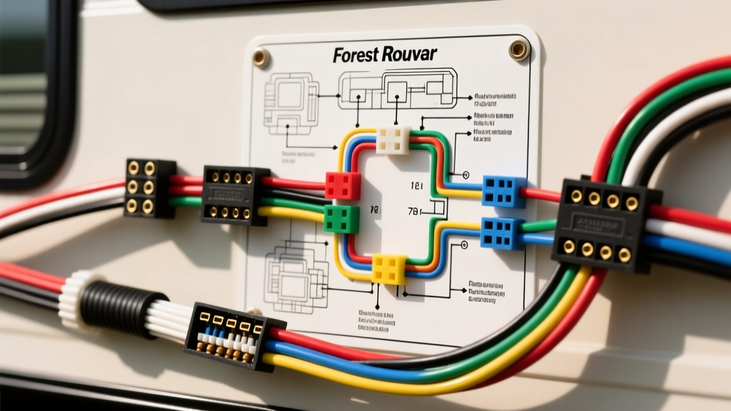
Understanding RVIA Color Codes vs. Standard Automotive Wiring
When you first unroll a schematic Forest River travel trailer wiring diagram, the most critical realization is that Recreational Vehicle Industry Association (RVIA) standards differ significantly from standard flat-4 automotive trailer wiring. While a standard 4-pin flat harness uses a brown wire for tail lights and yellow/green for turn signals, the 7-way RV blade connector standardizes entirely different color codes for the 12V auxiliary, electric brake, and lighting circuits. Misinterpreting these colors is the leading cause of blown tow vehicle fuses and malfunctioning electric brakes on Forest River models like the Cherokee, Wildwood, and Salem series.
According to the Recreational Vehicle Industry Association (RVIA), manufacturers must adhere to strict color-coding for the internal junction box (J-box) located on the A-frame. This J-box acts as the central nervous system for the trailer's electrical grid, translating the 7-way plug inputs to the respective axle brakes, breakaway switch, and exterior marker lights. Before cutting, stripping, or crimping any wires, you must map your physical wires to the schematic using the RVIA matrix below.
The 7-Way RV Blade Pinout and Junction Box Matrix
The following table outlines the exact pin configuration, RVIA wire color, and required American Wire Gauge (AWG) for a standard Forest River travel trailer 7-way schematic. Note that electric brakes and the 12V auxiliary charge line require heavier gauge wire to prevent voltage drop over the 25-to-35-foot run from the tow vehicle to the trailer axles.
| 7-Pin Clock Position | Function | RVIA Wire Color | Minimum AWG Size |
|---|---|---|---|
| 1:00 (Top Center) | 12V Auxiliary / Battery Charge | Black | 10 AWG |
| 3:00 (Right) | Right Turn / Stop | Brown | 12 AWG |
| 5:00 (Bottom Right) | Ground Return | White | 10 AWG |
| 7:00 (Bottom Left) | Left Turn / Stop | Red | 12 AWG |
| 9:00 (Left) | Tail / Running Lights | Green | 12 AWG |
| 11:00 (Top Left) | Electric Brakes | Blue | 10 AWG |
| Center | Auxiliary / Reverse Lights | Yellow | 12 AWG |
For comprehensive surface vehicle wiring standards, refer to the SAE J286 Surface Vehicle Standard, which dictates the physical pin spacing and voltage tolerances for the 7-way connector.
Step-by-Step Installation: A-Frame Junction Box to 7-Pin Plug
Replacing a damaged 7-way harness or upgrading the factory wiring on a Forest River travel trailer requires meticulous attention to grounding and circuit protection. Follow this practical installation guide to ensure your brake controller operates without voltage drop and your lighting circuits remain isolated.
Step 1: Defeating the Chassis Ground (The Forest River Flaw)
Many Forest River schematics show the white ground wire terminating to a ring terminal bolted directly to the steel A-frame. In practice, this is a massive failure point. Powder coating on the frame, combined with road salt and moisture, creates high resistance. This causes 'backfeed,' where applying the brakes makes the tail lights dimly illuminate. The Fix: Ignore the schematic's chassis ground point. Run a dedicated 10 AWG white wire from Pin 5 on the 7-way plug directly into the A-frame junction box ground bus bar. This ensures a clean, zero-resistance return path directly to the tow vehicle's battery negative terminal.
Step 2: Integrating the Breakaway Switch Safely
Forest River travel trailers are equipped with a DOT-mandated breakaway system. The schematic will show the breakaway switch wired in parallel with the electric brake circuit. Critical Warning: The blue wire from the breakaway switch must connect to the blue brake wire after the junction box, heading toward the axles. If you wire the breakaway switch to the blue wire before the J-box (on the harness side), a triggered breakaway event will send 12V backward through the harness and into your tow vehicle's brake controller, instantly destroying the controller's internal MOSFETs.
Step 3: Routing and Terminating the Molded 7-Way Harness
- Prep the Harness: Purchase a molded 7-way pigtail (minimum 8 feet). Strip back 3 inches of the outer black PVC jacket. Be extremely careful not to nick the 10 AWG blue and black wires.
- Install Circuit Protection: Install a 40-amp auto-reset circuit breaker on the 10 AWG black (12V auxiliary) wire within 18 inches of the tow vehicle battery, and a 30-amp breaker on the blue (brake) wire near the brake controller. The trailer side J-box does not typically house inline fuses for these main feeds.
- Terminate at the J-Box: Open the black plastic junction box on the A-frame. Strip 3/8 inch of insulation from each wire. Crimp on #10 and #12 AWG non-insulated ring terminals using a heavy-duty ratcheting crimper. Apply a layer of heat shrink tubing over the crimp barrel.
- Torque Specifications: Secure the ring terminals to the brass machine screws inside the J-box. Torque the terminal nuts to exactly 35-45 in-lbs. Over-tightening will strip the soft brass screws, while under-tightening will cause arcing and melt the plastic J-box housing.
- Weatherproofing: Pack the bottom half of the J-box with dielectric grease before sealing the lid. This prevents galvanic corrosion between the copper wire and brass terminals.
Diagnosing Common Schematic Discrepancies and Failure Modes
Even when you follow the schematic Forest River travel trailer wiring diagram perfectly, real-world manufacturing quirks can cause electrical gremlins. Here is how to troubleshoot the most common issues found in Forest River units.
Corrugated Loom Water Traps and Green Corrosion
Forest River often routes the main wiring harness from the A-frame J-box to the rear axle brakes through a black corrugated split-loom. While this protects against rock chips, the split seam faces upward, catching rain and highway spray. Water pools inside the loom, turning the wire harness into a wick. By the time the wiring reaches the Dexter or Lippert axles, the copper strands are often black with oxidation. The Fix: When servicing the brakes, cut back the split-loom, inspect the 10 AWG blue wire for green/white crust, and wrap the loom seams with automotive harness tape or spiral wrap to seal out moisture.
Backfeed and the 'Dim Tail Light' Syndrome
If your trailer's running lights illuminate when you press the brake pedal, or vice versa, you have a backfeed issue. On Forest River schematics, this is almost always caused by a corroded tail light socket on the rear of the trailer creating a bridge between the 12V (Green) and Turn/Brake (Red/Brown) circuits inside the bulb housing. Before tearing apart the A-frame J-box, pull the rear tail light lenses, clean the socket contacts with electrical contact cleaner, and apply a dab of silicone dielectric grease to the bulb bases.
Voltage Drop on Electric Brakes
If your brake controller in the cab reads 6.0V output, but a multimeter at the trailer's 7-way plug reads only 4.2V under load, you are suffering from severe voltage drop. This is often due to the factory using 12 AWG wire for the blue brake circuit instead of the required 10 AWG. Upgrading the entire blue brake run from the 7-pin to the J-box, and from the J-box to the axle magnets, to 10 AWG stranded copper will restore full braking torque and prevent the brake controller from throwing an 'S.H.' (Short Circuit) or 'O.L.' (Overload) error code.
Authoritative References
- Recreational Vehicle Industry Association (RVIA) - Guidelines for RV low-voltage electrical systems and color coding.
- SAE J286 Surface Vehicle Standard - Official specifications for trailer connector pinouts and physical dimensions.
- CURT Towing Electrical Guides - Practical installation matrices for 7-way RV blade connectors and breakaway switch integration.