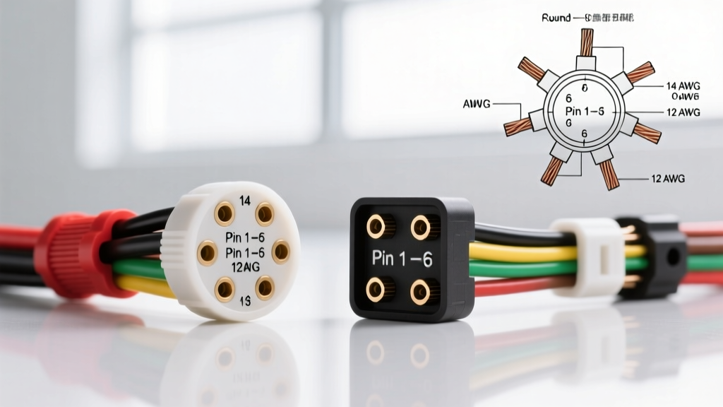
The Anatomy of a 6-Prong Towing System
When towing horse trailers, mid-sized travel trailers, or heavy utility equipment, the 6-prong connector bridges the gap between basic 4-pin lighting setups and full 7-pin RV configurations. A proper six prong trailer wiring diagram provides dedicated circuits for electric brakes, running lights, turn signals, and a 12-volt auxiliary power feed. However, not all 6-pin connectors are created equal. The two dominant configurations—the 6-Pin Round (RVIA standard) and the 6-Pin Square (legacy Winnebago/utility standard)—feature radically different pinouts and harness requirements. Selecting the wrong harness or misinterpreting the diagram can lead to catastrophic brake controller failure, voltage drop, or melted plug housings.
Decoding the Six Prong Trailer Wiring Diagram: Round vs. Square
Before purchasing a replacement harness or adapter, you must identify your connector style. According to the RV Industry Association (RVIA) and SAE J286 standards, the physical geometry dictates the circuit mapping.
6-Pin Round Connector (RV Standard) Pinout & Specs
The 6-way round connector is the most common configuration for modern horse trailers and older travel trailers. The pinout (viewed from the front of the trailer-side female plug) follows a specific clock-position layout:
- Center Pin: Ground (White) - 10 AWG
- 12 O'Clock: Tail/Running Lights (Brown) - 14 AWG
- 2 O'Clock: Left Turn/Stop (Yellow) - 14 AWG
- 4 O'Clock: Right Turn/Stop (Green) - 14 AWG
- 6 O'Clock: Electric Brakes (Blue) - 10 AWG
- 10 O'Clock: 12V Auxiliary Power (Red or Black) - 10 AWG
6-Pin Square Connector (Winnebago/Utility) Pinout & Specs
Primarily found on older Winnebago motorhomes, specialized utility trailers, and some agricultural equipment, the 6-pin square connector uses a completely different mapping. Attempting to plug a square connector into a round adapter without a hardwired re-pinning harness will instantly short the 12V auxiliary circuit to the electric brakes, potentially destroying your brake controller. Always verify the square pinout with a multimeter before applying power, as manufacturer variations exist in legacy square plugs.
Harness Selection Guide: Comparing Premium Wiring Kits
When replacing a damaged harness or upgrading from a 4-pin flat, the quality of the copper stranding and the jacket material dictate the lifespan of the wiring. Below is a comparison of top-tier 6-prong harness kits available on the market, evaluated on AWG compliance, casing durability, and application.
| Brand / Part Number | Connector Type | Wire Gauge (Main/Aux) | Jacket Material | Best Application |
|---|---|---|---|---|
| Curt 56196 | 6-Way Round | 10 AWG / 14 AWG | Flexible PVC | Standard RV & Horse Trailers |
| Hopkins 48035 | 6-Way Square | 12 AWG / 16 AWG | Rigid PVC | Legacy Winnebago & Utility |
| Bargman 50-67-006 | 6-Way Round (Heavy Duty) | 10 AWG (All Circuits) | Thermoplastic Elastomer (TPE) | Extreme Cold / Heavy Equipment |
Expert Note: If you tow in sub-freezing climates, avoid standard PVC jackets (like the Hopkins 48035). PVC becomes brittle and cracks below 20°F (-6°C), exposing copper to road salt and moisture. Opt for TPE-jacketed harnesses like the Bargman heavy-duty series, which remain pliable in extreme cold.
Wire Gauge (AWG) and Voltage Drop Considerations
A critical failure point in aftermarket six prong trailer wiring diagrams is the use of undersized wire for the electric brake and 12V auxiliary circuits. Electric brakes draw significant current—often 12 to 15 amps per axle when fully engaged. If your trailer has dual axles, the blue brake wire must carry up to 30 amps.
Using 14 AWG wire for the brake circuit over a 30-foot run results in severe voltage drop. According to Ohm's Law and standard copper resistance charts, a 30-amp load on 30 feet of 14 AWG wire will drop the voltage at the trailer axles to roughly 9.5 volts. This causes the brakes to engage weakly and generates excess heat in the wiring harness. Always ensure your selected harness uses a minimum of 10 AWG stranded copper for the White (Ground), Blue (Brakes), and Red/Black (12V Aux) circuits. For comprehensive electrical standards, refer to the Curt Manufacturing Wiring Guides and SAE J1128 specifications for low-tension automotive cable.
Troubleshooting Matrix: Real-World 6-Pin Failure Modes
Even with a correct wiring diagram, environmental factors and poor termination lead to specific electrical faults. Use this diagnostic matrix to troubleshoot common 6-prong connector issues.
| Symptom | Root Cause | Diagnostic Fix |
|---|---|---|
| Brake controller displays 'SH' (Short) or 'OL' (Overload) | Blue brake wire shorting to ground inside the plug housing due to melted insulation or moisture ingress. | Disassemble the 6-pin plug. Check for pinched wires near the strain relief. Apply dielectric grease to the pins. |
| Tail lights dim significantly when brake pedal is applied | 'Ground Bounce' caused by an undersized White ground wire (e.g., 14 AWG instead of 10 AWG) or corrosion on the center pin. | Upgrade the White ground wire to 10 AWG. Ensure the vehicle-side ground is bolted to bare chassis metal, not painted frame. |
| 12V auxiliary circuit fails to charge trailer breakaway battery | Voltage drop across the 10 O'Clock pin due to loose set-screw terminals or oxidation. | Strip wires back to clean copper. Re-tighten terminal screws to 15-20 in-lbs. Solder connections if crimping fails. |
| Left turn signal hyper-flashes on tow vehicle | High resistance in the Yellow circuit or a poor ground causing the vehicle's flasher relay to misinterpret the load. | Test continuity from the vehicle plug to the trailer lamp socket. Replace corroded bayonet sockets on the trailer. |
Expert Installation & Termination Standards
When hardwiring a new 6-prong harness to your trailer's junction box or directly to the lamps, the termination method is just as critical as the wire gauge. Follow these professional installation standards to ensure a weatherproof, vibration-resistant connection:
- Stripping and Prep: Strip exactly 3/8-inch of insulation from the stranded copper. Do not nick the outer strands, as this reduces the cross-sectional area and creates a localized hot spot.
- Terminal Crimping: Use closed-barrel, heat-shrink insulated ring terminals. Never use open-barrel or vinyl-insulated crimps in exterior trailer applications, as vibration will cause the wire to pull out.
- Set-Screw Torque: When securing wires into the brass terminal blocks of the 6-pin plug, torque the set screws to 15-20 in-lbs. Overtightening will shear the fine copper strands; undertightening will allow the wire to arc and melt the plug housing.
- Weatherproofing: Before closing the plug housing, pack the rear cavity with a high-quality silicone dielectric grease. This prevents capillary action from drawing moisture up the wire jacket into the connector pins.
By understanding the nuances between round and square configurations, adhering to strict AWG requirements, and utilizing proper termination techniques, you can build a 6-prong towing system that operates safely and reliably for years.