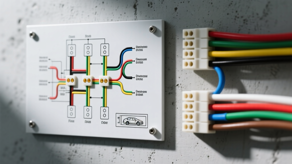
The Anatomy of the 7 Pin Flat Wiring Diagram
The 7 pin flat connector, universally known in the automotive and RV industries as the 7-way RV blade, is the standard interface for light-to-medium duty towing in North America. It provides the necessary circuits for tail lights, turn signals, electric trailer brakes, and a 12-volt auxiliary power feed. However, despite its widespread use, the 7 pin flat wiring diagram is frequently misunderstood, leading to catastrophic electrical failures, trailer brake lockups, and even vehicle fires.
Unlike the heavy-duty 7-way round connectors used in commercial and agricultural applications, the flat blade design relies on precise pin tension and specific wire gauge sizing to handle high-amperage loads safely. When installing, repairing, or troubleshooting a 7-way harness, relying on memory or assuming factory color codes are universal can result in severe safety hazards. This guide details the most critical wiring mistakes and the safety warnings every automotive electrical technician and DIY tower must know.
Standard SAE J286 7-Way RV Blade Pinout
Before addressing common errors, it is vital to establish the baseline standard. The SAE J286 standard, adopted by the Recreation Vehicle Industry Association (RVIA), dictates the physical pinout and color coding for the 7-way flat connector. Note that the pin numbering is standardized when looking at the vehicle-side socket (the female receptacle).
| Pin Number | Function | Standard Wire Color | Minimum Recommended AWG |
|---|---|---|---|
| Pin 1 | Ground Return (All Circuits) | White | 10 AWG (or 8 AWG) |
| Pin 2 | Tail / Running / Marker Lights | Brown | 14 AWG |
| Pin 3 | Left Turn Signal / Stop Lamp | Yellow | 14 AWG |
| Pin 4 | Right Turn Signal / Stop Lamp | Green | 14 AWG |
| Pin 5 | Electric Trailer Brakes | Blue | 10 AWG |
| Pin 6 | 12V Auxiliary Power / Battery Charge | Black (or Red) | 10 AWG |
| Pin 7 | Reverse Lights / Backup Alarm | Purple | 14 AWG |
Top 5 Catastrophic Wiring Mistakes to Avoid
Mistake 1: Swapping Pin 5 (Brakes) and Pin 6 (12V Aux)
This is arguably the most dangerous error when wiring a 7 pin flat diagram. Pin 5 is designed to receive a pulsed, variable-voltage signal from the tow vehicle's brake controller. Pin 6 provides a constant 12V hot lead from the vehicle's battery or alternator. If these two pins are swapped at the trailer junction box, the moment the vehicle is turned on, a constant 12 volts is sent directly to the trailer's electric brake magnets.
The Physics of the Failure: A standard 12-inch electric brake magnet has a resistance of roughly 3.2 to 3.5 ohms. According to Ohm's Law (I = V/R), applying a constant 12V to a 3.2-ohm magnet draws approximately 3.75 amps. On a dual-axle trailer with four brakes, this creates a continuous 15-amp draw. Because the brakes are constantly engaged, the magnets will overheat within minutes, melting the internal nylon bobbin, destroying the braking surface, and potentially igniting the rubber grease seals on the axle hubs. Simultaneously, the brake controller's variable output is sent to the trailer's 12V auxiliary line, which can fry interior RV electronics, lithium battery management systems (BMS), or breakaway switch batteries.
Mistake 2: Undersizing the Pin 1 Ground Return
Many DIY installers use 14 AWG or 16 AWG wire for the Pin 1 ground because it matches the lighting circuits. This is a severe safety violation. In a 7-way flat system, the single white ground wire must carry the return current for every active circuit on the trailer.
If you are driving at night with the tail lights on (5 amps), applying the brakes (15 amps to the magnets), and charging a trailer battery (10 amps), the ground wire must safely carry 30 amps back to the vehicle chassis. A 14 AWG copper wire is only rated for roughly 15 amps in a bundled chassis harness. Pushing 30 amps through it will cause severe voltage drop, leading to flickering lights, erratic brake controller behavior (often throwing 'SH' or 'OL' error codes), and eventually, thermal melting of the wire insulation. Always use a minimum of 10 AWG, and ideally 8 AWG, for the main ground trunk line.
Mistake 3: Blindly Trusting Non-Standard Wire Colors
While the SAE J286 standard dictates specific colors, the market is flooded with cheap, imported replacement harnesses and junction boxes that ignore these codes entirely. A common trap is assuming the blue wire on a replacement pigtail is always the brake circuit. On some non-compliant harnesses, blue is used for the 12V auxiliary, and black is used for the brakes.
The Fix: Never wire a trailer junction box by color alone. Always use a digital multimeter or a dedicated circuit tester to trace the physical pin position on the molded plug. Insert a continuity tester probe into the physical Pin 5 slot of the male plug, and trace the wire to verify its function before crimping it to the trailer's brake feed.
Mistake 4: Overloading the 12V Auxiliary Circuit (Pin 6)
Pin 6 is frequently misused by off-road and overland enthusiasts to power high-draw accessories like electric trailer winches, air compressors, or high-wattage DC-to-AC inverters. The 12V auxiliary pin on a standard 7-way flat connector is physically limited by the brass contact surface area inside the plastic housing. Most OEM tow packages protect this circuit with a 20A or 30A fuse under the hood.
Attempting to pull 60+ amps through Pin 6 to run a trailer winch will cause the brass contacts to arc, pit, and generate extreme heat. This thermal runaway will melt the plastic housing of both the vehicle socket and the trailer plug, fusing them together and destroying the connector. For high-draw accessories, bypass the 7-way connector entirely and run a dedicated, fused 2 AWG or 4 AWG cable directly from the vehicle battery to an Anderson Powerpole or quick-disconnect solenoid on the trailer tongue.
Mistake 5: Using Conductive Grease Instead of Dielectric Grease
Corrosion is the enemy of the 7-way flat connector, but using the wrong chemical protection accelerates failure. Some mechanics mistakenly apply anti-seize or copper-based conductive grease to the connector pins to prevent rust. Because the pins on a 7-way blade are spaced only millimeters apart, conductive grease will squeeze out under insertion pressure and bridge the gaps between adjacent pins. This creates a direct short circuit between the 12V hot lead, the ground, and the sensitive brake controller output, instantly blowing fuses or destroying the brake controller module. Always use a high-quality, non-conductive silicone dielectric grease to seal out moisture without allowing cross-circuit continuity.
Safety Warnings: Frame Grounding and DOT Compliance
Beyond the plug itself, the Department of Transportation (DOT) and the RVIA safety guidelines mandate strict adherence to grounding practices at the trailer frame. A common failure mode is attaching the white ground wire to a painted or powder-coated section of the trailer tongue. Paint acts as an insulator. The resulting high-resistance ground forces the trailer's lighting and brake circuits to seek an alternative return path, often backfeeding through the trailer hitch ball. This causes erratic braking, damages the vehicle's CAN-bus electrical system, and creates a severe shock hazard when disconnecting the trailer.
Proper Grounding Protocol: 1. Grind away all paint, powder coat, and rust down to bare, shiny steel. 2. Use a heavy-duty steel or brass terminal lug, secured with a Grade 8 bolt and a star washer to bite into the metal. 3. Apply a layer of anti-oxidant compound (such as Noalox) over the bare metal before tightening the lug to prevent galvanic corrosion, especially on aluminum trailer frames.
AWG Wire Sizing Chart for 7-Pin Harnesses
Voltage drop is a critical factor in trailer wiring, particularly for electric brakes. If the voltage at the furthest brake magnet drops below 10V due to undersized wiring, the magnet will not engage with enough force to stop the trailer, leading to dangerous pushing of the tow vehicle during emergency stops. Use the following chart to select the correct wire gauge based on the total length of the harness run from the vehicle battery to the furthest trailer axle.
| Circuit Function | Max Expected Amperage | AWG (Under 25 ft Run) | AWG (25 ft to 50 ft Run) |
|---|---|---|---|
| Ground Return (Pin 1) | 30A - 40A | 10 AWG | 8 AWG |
| Electric Brakes (Pin 5) | 15A - 18A | 10 AWG | 8 AWG |
| 12V Auxiliary (Pin 6) | 20A - 30A | 10 AWG | 8 AWG |
| Tail / Marker Lights (Pin 2) | 5A - 8A | 14 AWG | 12 AWG |
| Turn / Stop Signals (Pins 3, 4) | 4A - 6A | 14 AWG | 12 AWG |
| Reverse / Backup (Pin 7) | 5A - 10A | 14 AWG | 12 AWG |
Authoritative References & Further Reading
To ensure your towing setup is compliant and safe, always consult the primary engineering standards and industry guidelines. For detailed specifications on connector physical dimensions and electrical tolerances, refer to the SAE J286 Standard Documentation. For comprehensive troubleshooting steps and OEM-specific tow package wiring schematics, the etrailer Wiring FAQ and Technical Guide provides excellent vehicle-specific pinout verification resources. Finally, ensure your trailer's braking and lighting systems meet all federal motor vehicle safety standards (FMVSS) as outlined by the NHTSA.