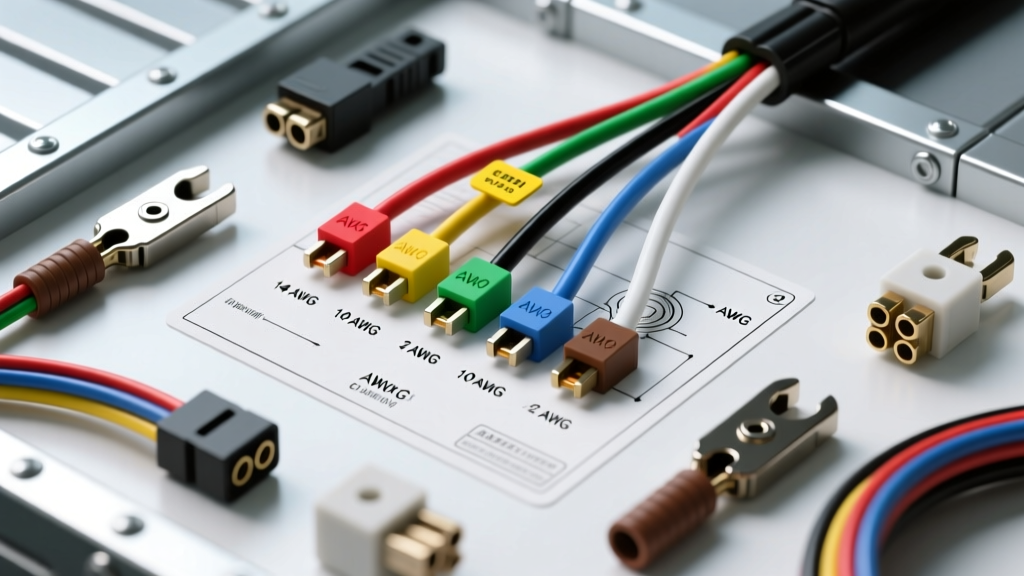
Understanding the 7 Pin Electric Trailer Brake Wiring Diagram
For beginners stepping into the world of towing, transitioning from a simple 4-pin flat connector to a 7-way RV blade connector can feel overwhelming. However, mastering the 7 pin electric trailer brake wiring diagram is an essential fundamental for anyone towing heavy loads, horse trailers, or travel trailers. The 7-way connector not only handles standard lighting functions but also provides the critical circuits required for electric trailer brakes, auxiliary 12V power, and reverse lights.
In this beginner-friendly guide, we will break down the industry-standard SAE J286 pinout configuration, explain the physics behind wire gauge selection, and walk you through the exact integration of a proportional brake controller. By the end of this article, you will have the technical confidence to wire, test, and troubleshoot your trailer's electric braking system.
The Standard 7-Way RV Blade Pinout Configuration
The 7-way RV blade connector is the undisputed standard for heavy-duty towing in North America. When looking at the face of the trailer-side plug (the male end), the pins are arranged in a specific circular pattern. Automotive electrical technicians often use the 'clock face' method to identify pins, with the center pin acting as the 12V auxiliary power source.
According to the SAE J286 standard for trailer electrical connectors, specific wire colors are assigned to each function to ensure universal compatibility between tow vehicles and trailers.
7-Pin Connector Specification Chart
| Pin Position | Function | Standard Wire Color | Minimum AWG Size | Circuit Protection |
|---|---|---|---|---|
| Pin 1 (7 o'clock) | Ground Return | White | 8 AWG | N/A (Chassis Ground) |
| Pin 2 (11 o'clock) | Tail / Running Lights | Brown | 14 AWG | 15A Fuse |
| Pin 3 (9 o'clock) | Left Turn / Stop | Yellow | 14 AWG | 15A Fuse |
| Pin 4 (3 o'clock) | Right Turn / Stop | Green | 14 AWG | 15A Fuse |
| Pin 5 (1 o'clock) | Electric Brakes Output | Blue | 10 or 12 AWG | 30A Circuit Breaker |
| Pin 6 (Center) | 12V Aux / Battery Charge | Black | 10 or 12 AWG | 30A Circuit Breaker |
| Pin 7 (5 o'clock) | Backup / Reverse Lights | Purple | 14 AWG | 15A Fuse |
Wire Sizing Fundamentals: Why AWG Matters for Electric Brakes
One of the most common beginner mistakes is using undersized wire for the electric brake circuit (Pin 5) and the auxiliary power circuit (Pin 6). While 14 AWG or 16 AWG wire is perfectly adequate for low-amperage LED trailer lights, electric brake magnets draw significant current.
The Physics of Voltage Drop
A standard 10-inch electric trailer brake magnet draws approximately 3.0 to 3.5 amps at 12 volts. If you are towing a tandem-axle trailer with four brake assemblies, the total current draw can exceed 12 amps. If you use 14 AWG wire for a 25-foot run from the brake controller to the furthest trailer axle, you will experience severe voltage drop. According to Ohm's Law, increased resistance in undersized wires results in a drop in voltage reaching the brake magnets, leading to weak, inconsistent braking performance and overheated wires.
- 14 AWG Wire: Maximum recommended run for brakes is 10 feet. (Not recommended for full brake circuits).
- 12 AWG Wire: Suitable for single-axle trailers (2 brakes) with runs up to 20 feet.
- 10 AWG Wire: The professional standard for tandem-axle and triple-axle trailers. Ensures maximum voltage delivery to the brake magnets over long distances.
Pro Tip: Always use stranded copper wire, never solid copper. Solid wire will fracture and break due to the constant vibration and flexing of the trailer chassis.
Brake Controller Integration: Wiring the Brain
The 7 pin electric trailer brake wiring diagram is only half of the equation; the other half is the in-cabin brake controller. Whether you are installing a time-delayed or proportional controller (like the popular Tekonsha Prodigy P2 or P3), the controller relies on four primary wires to function correctly.
Controller to Vehicle Wiring Map
- White Wire (Ground): Must be attached to a clean, bare metal surface on the vehicle's chassis. Use a ring terminal and secure it with a self-tapping sheet metal screw or an existing chassis bolt. Torque to 10-15 ft-lbs to prevent ground loops.
- Black Wire (12V Power Input): Routes directly to the positive terminal of the vehicle's battery. CRITICAL: You must install a 20A or 30A automotive circuit breaker within 18 inches of the battery positive terminal to protect against catastrophic shorts.
- Red Wire (Stoplight Switch): Connects to the 'cold' side of the vehicle's stoplight switch. This wire tells the controller when you press the brake pedal. It should only receive 12V when the brakes are applied. Never connect this to the tail light circuit.
- Blue Wire (Brake Output): Routes from the controller, through the firewall, under the chassis, and terminates at Pin 5 of the 7-way socket.
The Breakaway Switch: Your Critical Safety Net
No 7 pin electric trailer brake wiring diagram is complete without addressing the breakaway switch. This device is legally required in most states for trailers equipped with electric brakes. If the trailer accidentally detaches from the hitch, a lanyard pulls a pin from the switch, activating the trailer brakes independently of the tow vehicle.
The breakaway system relies on a dedicated 12V battery mounted on the trailer tongue. The center pin of your 7-way connector (Pin 6, Black Wire) provides a trickle charge to this battery while you drive. When the pin is pulled, the breakaway switch sends full battery voltage directly into the Blue Wire circuit, locking the trailer brakes. Ensure your breakaway battery is a minimum of 12V 5Ah sealed lead-acid (SLA) or AGM type, and test it every six months.
Real-World Troubleshooting & Failure Modes
Even with a perfect installation, environmental factors and wear can cause electrical gremlins. Here is a diagnostic decision tree for the most common electric brake failures.
Symptom: Brake Controller Displays 'SH' or 'OL'
- Cause: 'SH' indicates a Short to ground or 12V on the Blue Wire. 'OL' indicates an Overload (too many brake magnets or a seized magnet).
- Fix: Inspect the 7-way plug for corrosion. Check the Blue Wire where it passes through the trailer tongue; the insulation often rubs bare against the steel frame, causing a short. Use a multimeter to test continuity between the Blue Wire and the White Ground wire.
Symptom: Brakes Lock Up Immediately Upon Plugging In
- Cause: The 12V Auxiliary power (Pin 6, Black) is bleeding into the Brake Output (Pin 5, Blue). This is almost always caused by moisture and green corrosion inside the trailer-side 7-way plug, creating a conductive bridge between the center pin and the 1 o'clock pin.
- Fix: Disassemble the trailer plug, clean the terminals with electrical contact cleaner, apply dielectric grease, and reassemble. If the plastic housing is cracked, replace the entire plug.
Symptom: Trailer Lights Flicker or Dim When Brakes are Applied
- Cause: A poor ground connection on Pin 1 (White Wire). When the high-amperage brake magnets engage, the current seeks the path of least resistance. If the main ground is weak, the current back-feeds through the tail light ground wires, causing the lights to flicker.
- Fix: Do not rely on the hitch ball for a ground. Ensure the White Wire on both the vehicle and trailer is bolted directly to the chassis. Sand away paint, rust, and undercoating to expose bare steel before attaching the ring terminal. For heavy trailers, consider running a dedicated 8 AWG ground wire directly from the vehicle chassis to the trailer chassis.
Final Thoughts and Maintenance
Understanding the 7 pin electric trailer brake wiring diagram transforms towing from a stressful chore into a safe, predictable experience. Always invest in high-quality, jacketed trailer wiring harnesses that protect individual wires from UV exposure and road debris. For further reading on heavy-duty towing electrical standards, consult the CURT Manufacturing Towing Guides or your vehicle's specific OEM upfitter documentation.
Before every long trip, perform a visual inspection of your 7-way connectors, apply a light coat of dielectric grease to the pins to repel moisture, and use a digital multimeter to verify that your brake output circuit is delivering a full 12 volts to the trailer axles.