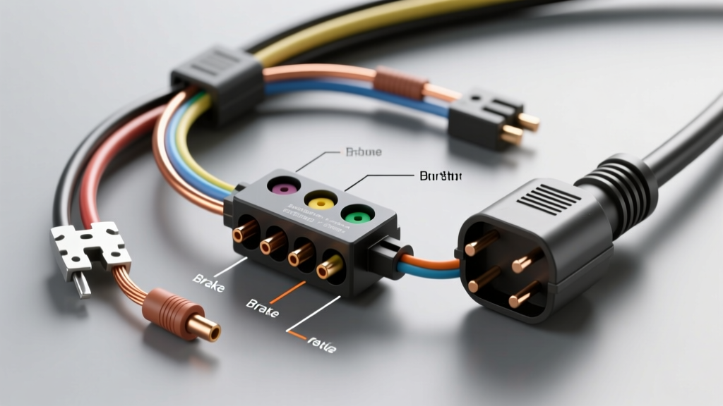
Project Overview: Upgrading from 4-Way Flat to 7-Way RV Blade
Upgrading a light-duty truck, SUV, or heavy-duty tow rig from a standard 4-way flat connector to a 7-way RV blade is one of the most impactful towing modifications you can perform. While the 4-way flat handles basic lighting (tail, left turn/stop, right turn/stop, and ground), it completely lacks the circuitry required for electric trailer brakes, 12V auxiliary power, and reverse lockout solenoids. For anyone towing enclosed cargo trailers, horse trailers, or travel trailers exceeding 3,000 lbs, this upgrade is not just a convenience—it is a critical safety requirement.
This comprehensive modification guide provides a complete trailer electrical connector wiring diagram and step-by-step execution protocols. We will cover the integration of heavy-gauge brake circuits, auxiliary charging lines, and the proper termination of the 7-way socket to meet SAE J286 and RVIA standards.
Bill of Materials and Tooling Requirements
Before cutting into your factory harness, gather the correct automotive-grade materials. Avoid cheap, pre-molded harnesses from big-box stores; their internal wire gauges are often undersized, leading to severe voltage drop over long wheelbases.
- 7-Way RV Socket: Pollak PK11898 or Hopkins 48425 (metal housing preferred for durability).
- Primary Wire (10 AWG): Black (12V Aux) and Blue (Electric Brakes). Minimum 25 feet.
- Primary Wire (12 AWG or 14 AWG): For reverse lights or auxiliary backup circuits.
- Circuit Breakers: 40-Amp Type 1 Auto-Reset (Brake Circuit), 30-Amp Type 1 Auto-Reset (12V Aux Circuit).
- Splice Connectors: Solder-seal heat shrink butt splices (16-14 AWG and 12-10 AWG).
- Tools: Wire strippers, heavy-duty crimpers, heat gun, digital multimeter, dielectric grease, and split-loom tubing.
The Core Trailer Electrical Connector Wiring Diagram (7-Way RV Blade)
When referencing a standard trailer electrical connector wiring diagram, technicians must note a critical industry quirk: the wire colors on the plug face (male side) follow a strict SAE standard, but the replacement harnesses (female side) often use different colored jackets. Always verify continuity with a multimeter rather than trusting the wire jacket color blindly. The table below outlines the standard pinout for the 7-Way RV blade socket as viewed from the wiring terminal side.
| Pin / Clock Position | Function | Standard Wire Color | Minimum AWG | Circuit Protection |
|---|---|---|---|---|
| Pin 1 (7:00) | Ground (Chassis) | White | 10 AWG | N/A (Direct to Chassis) |
| Pin 2 (5:00) | Electric Brakes | Blue | 10 AWG | 40A Auto-Reset Breaker |
| Pin 3 (1:00) | Tail / Running Lights | Green | 16 AWG | 15A Fuse (Factory) |
| Pin 4 (11:00) | 12V Auxiliary Power | Black | 10 AWG | 30A Auto-Reset Breaker |
| Pin 5 (9:00) | Left Turn / Stop | Red | 16 AWG | 20A Fuse (Factory) |
| Pin 6 (3:00) | Right Turn / Stop | Brown | 16 AWG | 20A Fuse (Factory) |
| Pin 7 (Center) | Reverse Lights / Aux | Yellow | 14 AWG | 15A Inline Fuse |
Step-by-Step Wiring Execution & Splice Protocols
Step 1: Tapping the Existing 4-Way Harness
Locate the factory 4-way flat connector near the rear bumper. Rather than using a plug-and-play adapter, hardwiring the new 7-way socket ensures a more reliable connection and eliminates the failure point of an intermediate adapter block. Cut the factory 4-way connector off, leaving enough wire to work with. Strip back the insulation to reveal the four lighting circuits (typically Brown for tail, Green for right turn, Yellow for left turn, and White for ground). Use 16-14 AWG solder-seal heat shrink butt connectors to splice the corresponding 16 AWG wires from your new 7-way harness to the factory lighting circuits. Apply heat until the internal solder melts and the outer adhesive lining seals the splice.
Step 2: Routing the Heavy-Gauge Brake and Battery Circuits
The most critical part of this modification is routing the 10 AWG Blue (brakes) and 10 AWG Black (12V aux) wires from the rear socket to the front engine bay. Route these wires along the inside of the vehicle's frame rail. Maintain a minimum clearance of 6 inches from any exhaust components to prevent heat degradation of the wire insulation. Secure the wires using UV-resistant zip ties or adhesive-backed wire clips every 12 to 18 inches. Where the wires pass through metal crossmembers or the firewall, use rubber grommets to prevent chafing and short circuits. Wrap the entire run in split-loom tubing for added abrasion resistance.
Step 3: Under-Hood Termination and Circuit Breakers
Do not connect heavy-gauge circuits directly to the battery without overcurrent protection. Mount the 40-Amp and 30-Amp Type 1 auto-reset circuit breakers on the inner fender well.
- Brake Circuit (Blue, 10 AWG): Connect to the 'AUX' (load) post of the 40-Amp breaker. Run a short jumper wire from the 'BAT' (source) post to the positive battery terminal.
- 12V Aux Circuit (Black, 10 AWG): Connect to the 'AUX' post of the 30-Amp breaker, with a jumper to the positive battery terminal.
- Ground Circuit (White, 10 AWG): Terminate with a heavy-duty ring terminal and bolt directly to a clean, bare-metal point on the chassis or engine block. Apply dielectric grease to the terminal to prevent galvanic corrosion.
Integrating the Proportional Brake Controller
If your modification includes installing an aftermarket proportional brake controller (such as a Tekonsha Prodigy or Redarc Tow-Pro), the blue 10 AWG wire you just routed serves as the output to the trailer brakes. You will need to wire the controller's pigtail under the dash. According to Tekonsha Installation Guides, the controller requires four connections: 1. White: Ground to chassis. 2. Black: 12V power (via a 20A or 30A inline fuse) to the battery. 3. Red: Stoplight switch signal (tapped from the cold side of the brake pedal switch, ensuring it only receives 12V when the pedal is depressed). 4. Blue: Output to the rear 7-way socket (connects to the blue 10 AWG wire routed under the vehicle).
Ensure all dash connections are crimped with insulated terminals and secured with electrical tape or heat shrink to prevent them from vibrating loose behind the kick panels.
Common Modification Pitfalls and Voltage Drop Diagnostics
Even with a perfect trailer electrical connector wiring diagram, real-world installations often encounter specific failure modes. Here is how to diagnose and fix the most common upgrade pitfalls:
Symptom: Trailer Breakaway Battery Fails to Charge
Cause: Voltage drop on the 12V auxiliary circuit (Black wire). Many pre-packaged harnesses use 12 AWG wire for the auxiliary pin. Over a 20-foot run from the engine bay to the rear bumper, 12 AWG wire experiences significant voltage drop, delivering less than 12V to the trailer's breakaway battery or RV house bank. Fix: Always use 10 AWG (or even 8 AWG for long-bed trucks) for the black auxiliary wire. If the voltage at the socket reads below 13.2V with the engine running, consider installing a DC-DC battery charger in the trailer rather than relying on the tow vehicle's alternator directly.
Symptom: Brake Controller Displays 'OL' (Overload) or 'SH' (Short)
Cause: A short to ground in the blue brake output wire, or an inadequate ground on the white wire. Fix: Disconnect the blue wire at the 7-way socket and at the brake controller. Use a multimeter to check for continuity between the blue wire and the chassis. If continuity exists, the wire is pinched against the frame. Furthermore, ensure the white ground wire is not simply bolted over painted metal; scrape away paint and primer to achieve bare-metal contact, and torque the ground bolt to 15-20 lb-ft.
Symptom: Trailer Lights Flicker or Dim When Brakes are Applied
Cause: Ground bounce or insufficient grounding at the socket. The 4-way lighting circuits rely heavily on the white ground wire to complete the circuit. If the ground path has high resistance, applying the brakes (which draw significant amperage) forces the lighting current to seek an alternative ground path, backfeeding through the bulb filaments. Fix: Clean the socket pins with electrical contact cleaner. Apply a liberal amount of dielectric grease inside the 7-way socket to displace moisture and prevent copper oxidation. Verify that the trailer-side plug is also wired correctly and that its ground wire is securely bonded to the trailer tongue.
Final Testing and Validation
Before connecting a trailer, perform a static bench test of the newly installed 7-way socket. Turn on the tow vehicle's headlights and verify 12V+ at the Green (Tail) pin using a multimeter. Have an assistant press the brake pedal while you test the Red (Left) and Brown (Right) pins. Finally, manually slide the brake controller override lever to verify that 12V+ is present at the Blue (Brake) pin. By adhering strictly to these AWG specifications, routing protocols, and SAE standards, your 7-way upgrade will provide years of reliable, heavy-duty towing service. For further reference on RV-specific electrical codes and battery charging standards, consult the RVIA technical bulletins.