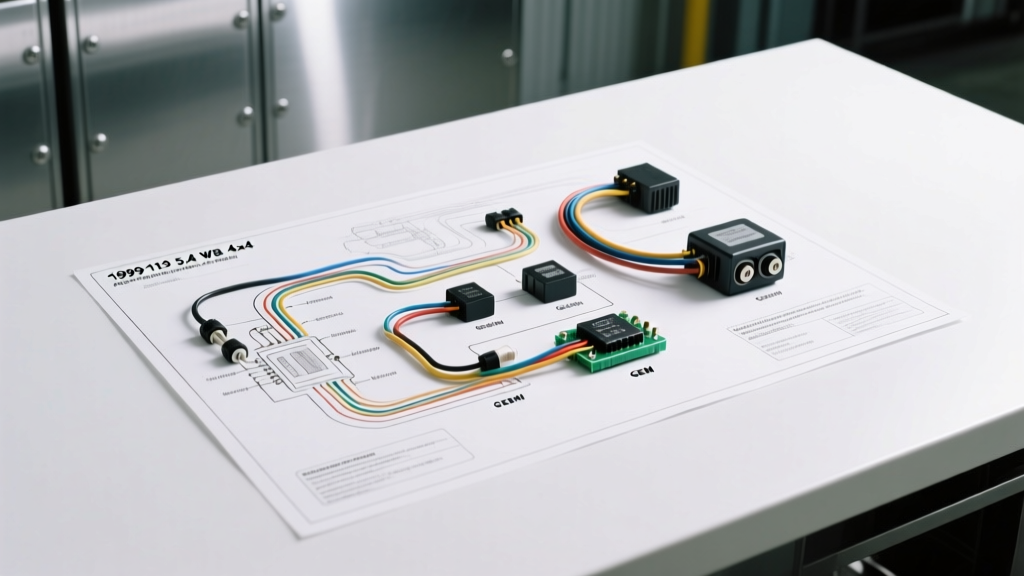
Understanding the 1999 F-150 5.4L Electrical Architecture
The 1999 Ford F-150 equipped with the 5.4L 2-valve Triton V8 and the BorgWarner 4406 transfer case represents a specific era of Ford's electrical engineering. Unlike modern trucks utilizing high-speed CAN bus networks, the 1999 model year relies heavily on the Generic Electronic Module (GEM) for body and 4x4 controls, while the Powertrain Control Module (PCM) manages the Coil-on-Plug (COP) ignition and fuel delivery. When utilizing a 1999 F150 5.4 V8 4x4 wiring diagram, technicians must understand that the 4x4 engagement is not vacuum-actuated like older F-Series trucks; it is entirely electronic, relying on the GEM, a shift motor, and a contact plate sensor.
This guide provides a step-by-step troubleshooting flow designed for automotive electricians and advanced DIYers. We will bypass generic advice and dive directly into wire colors, AWG specifications, and PCM pinouts to solve the most common electrical failures on this platform.
Troubleshooting Flow 1: 4x4 Transfer Case & GEM Module
Symptom: The 4x4 dash indicator flashes continuously, the truck is stuck in 2WD, or the transfer case engages erratically without driver input.
According to NHTSA Technical Service Bulletin 01-19-6, water intrusion into the GEM module is a primary failure point for 1997-2003 F-150s. Follow this diagnostic decision tree before replacing expensive transfer case components.
Step 1: Verify Power and Ground at the GEM
- Check Fuse 14 (20A) in the interior fuse panel. This fuse supplies the GEM and the 4x4 shift motor. If blown, do not simply replace it; you have a short to ground in the Light Blue/Red (LB/RD) circuit.
- Inspect the GEM Module: Located behind the radio and HVAC control panel. Remove the GEM and inspect the 36-pin and 42-pin connectors for green copper sulfate corrosion. If moisture is present, reseal the windshield cowl and replace the GEM.
- Verify GEM Grounds: Check the Black/White (BK/WT) wire at GEM Pin 14. Perform a voltage drop test to the negative battery terminal. A reading above 0.1V indicates a corroded ground splice under the dash.
Step 2: Test the BorgWarner 4406 Shift Motor & Contact Plate
If the GEM is dry and powered, the fault lies at the transfer case. The shift motor contains a relay pack and a contact plate that tells the GEM the current position of the shift forks (2WD, 4WD High, 4WD Low).
- Disconnect the 6-pin shift motor connector.
- Check VPWR: Probe Pin 1 (Red/Light Green) with a multimeter. It should read battery voltage (12.4V+).
- Check Ground: Probe Pin 2 (Black/Yellow). Verify continuity to chassis ground (less than 1 ohm).
- Actuator Test: Apply 12V directly to Pin 3 and ground to Pin 4 to manually drive the motor. If the motor clicks but doesn't turn, the internal nylon gear is stripped.
| Pin | Function | Wire Color | AWG | Diagnostic Value |
|---|---|---|---|---|
| 1 | Shift Motor Power (VPWR) | Red / Light Green (RD/LG) | 14 AWG | 12.4V Key-On |
| 2 | Shift Motor Ground | Black / Yellow (BK/YL) | 14 AWG | < 1.0 Ohm to Chassis |
| 3 | Contact Plate Sense A | Light Blue / Black (LB/BK) | 18 AWG | 5V Reference / Pull-up |
| 4 | Contact Plate Sense B | White / Red (WT/RD) | 18 AWG | 5V Reference / Pull-up |
| 5 | Contact Plate Sense C | Orange / Light Green (OG/LG) | 18 AWG | 5V Reference / Pull-up |
| 6 | Contact Plate Sense D | Tan / Orange (TN/OG) | 18 AWG | 5V Reference / Pull-up |
Note: If the motor turns but the dash light still flashes, the internal contact plate carbon tracks are worn, causing the GEM to lose positional awareness. Replace the contact plate sensor assembly.
Troubleshooting Flow 2: 5.4L 2V COP Ignition System
Symptom: Random or specific cylinder misfires (P0300-P0308), rough idle, and hesitation under load. The 1999 5.4L 2-valve engine uses a Coil-on-Plug (COP) system, eliminating spark plug wires but introducing new wiring harness vulnerabilities.
Step 1: Inspect the VPWR Feed and Harness Chafing
- The COP coils receive power from the PCM Power Relay via a Red/Light Green (RD/LG) wire. This circuit is protected by a 30A fuse in the under-hood distribution box.
- Check for Harness Chafing: The main engine harness frequently rubs against the rear of the passenger side cylinder head or the EGR tube. Inspect the loom near the firewall. A short here will blow the PCM power relay fuse and kill all injectors and coils simultaneously.
- Measure voltage at the COP connector (Red/Light Green wire) with the engine cranking. It must not drop below 10.5V. If it drops, perform a voltage drop test on the 10 AWG feed wire from the CCRM (Constant Control Relay Module).
Step 2: Verify PCM Trigger Signals
The PCM grounds the primary side of the ignition coil to fire the plug. A failure in the trigger wire will result in a dead cylinder. Use a logic probe or an oscilloscope to verify the square wave signal from the PCM.
| Cylinder | PCM Pin | Wire Color at Coil | Expected Oscilloscope Pattern |
|---|---|---|---|
| Cyl 1 | 52 | Light Blue / Red (LB/RD) | 12V dwell, drop to 0V on fire |
| Cyl 2 | 54 | White / Red (WT/RD) | 12V dwell, drop to 0V on fire |
| Cyl 3 | 55 | Tan / Red (TN/RD) | 12V dwell, drop to 0V on fire |
| Cyl 4 | 56 | Yellow / Light Green (YL/LG) | 12V dwell, drop to 0V on fire |
| Cyl 5 | 78 | Orange / Light Green (OG/LG) | 12V dwell, drop to 0V on fire |
| Cyl 6 | 79 | Dark Green / Orange (DG/OG) | 12V dwell, drop to 0V on fire |
| Cyl 7 | 80 | White / Purple (WT/VT) | 12V dwell, drop to 0V on fire |
| Cyl 8 | 81 | Dark Blue / Light Green (DB/LG) | 12V dwell, drop to 0V on fire |
Expert Insight: If the PCM trigger signal is present but the coil is not firing, the issue is internal to the coil or the spark plug boot. The 5.4L 2V engines are notorious for spark plug boot degradation. Moisture enters the well, causing the high-voltage secondary arc to track down the side of the plastic boot to the cylinder head ground instead of jumping the spark plug gap. Always apply dielectric grease to the inside of the COP boot during reassembly.
Critical Wire Gauges & Connector Specifications
When repairing or extending wires on the 1999 F-150, adhering to SAE J1128 standards for low-tension primary cable is critical to prevent voltage drop and electrical fires.
- Battery to Starter Motor: 1/0 AWG stranded copper. Torque starter B+ terminal to 10 Nm (89 lb-in).
- Alternator B+ Output: 8 AWG. Protected by a 175A Mega Fuse. Inspect the ring terminal for heat discoloration, a common failure point due to under-hood vibration.
- PCM Power & Grounds: 16 AWG to 18 AWG. The PCM grounds are located on the right rear of the engine block. Remove, wire-brush, and reinstall with anti-seize to ensure a clean logic ground for the COP dwell circuits.
- Connectors: Ford uses weather-sealed D-Sub and Weather-Pack style connectors for under-hood sensors. Never use twist-on wire connectors or standard electrical tape under the hood. Use adhesive-lined heat shrink and Deutsch-style crimp pins for any harness repairs.
Expert Tips for Using the Factory EVTM
To master the 1999 F150 5.4 V8 4x4 wiring diagram, you must learn to read Ford's Electrical and Vacuum Troubleshooting Manual (EVTM). The EVTM uses a specific grid system (e.g., Cell 142, Column B). When tracing the 4x4 shift motor circuits, cross-reference the GEM pinout chart with the Transfer Case Control schematic. Community resources like the F150Online Electrical System Archives are invaluable for locating factory EVTM PDF scans and decoding Ford's cryptic wire color abbreviations (e.g., BK/OR for Black with Orange tracer).
By following this structured troubleshooting flow, verifying voltage drops instead of merely checking for continuity, and respecting OEM wire gauge specifications, you can accurately diagnose and repair the complex electrical gremlins inherent to the 10th-generation F-150 platform.