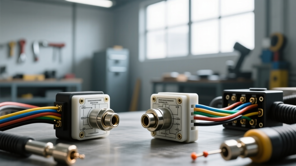
The Anatomy of a 3-Pin Horn Relay: Where is Pin 85?
When enthusiasts and technicians pull up a 3 pin horn relay wiring diagram, confusion often arises regarding the missing pin. Standard ISO mini relays utilize four or five pins (30, 85, 86, 87, and 87a). However, in many OEM applications, classic vehicle restorations, and heavy-duty aftermarket solenoid-style relays, a 3-pin configuration is employed. In this setup, the relay coil's ground path (traditionally Pin 85) is internally bonded to the metal mounting bracket of the relay casing.
This means the three visible spade terminals serve the following functions:
- Pin 30 (Common / B+): Direct 12V power from the battery.
- Pin 86 (Coil Trigger): Switched 12V signal from the steering wheel horn button.
- Pin 87 (Normally Open / Load): Output power to the horn(s).
Understanding this bracket-ground architecture is the first step in avoiding catastrophic wiring failures. If you treat a 3-pin relay like a standard 4-pin relay, your circuit will fail to energize, or worse, create a short-to-ground scenario.
Critical Safety Warnings for High-Amperage Horn Circuits
Automotive horns are inductive loads that draw massive current spikes upon startup. A single standard disc horn draws 5 to 8 amps, while dual Fiamm or Hella air horns can pull 20 to 30 amps continuously. According to Littelfuse automotive relay specifications, inductive loads can generate voltage spikes up to 10 times the system voltage when the circuit is opened. Before touching a wire stripper, heed these non-negotiable safety warnings:
- Always Disconnect the Battery: Disconnect the negative terminal and isolate it. A short across the main 12V feed (Pin 30) can weld a wrench to the chassis and instantly ignite the wiring harness.
- Fuse Placement is Mandatory: Per SAE J1284 standards, the main inline fuse must be located within 18 inches of the battery positive terminal. Fusing the wire near the relay leaves the entire run from the battery unprotected and prone to causing an engine bay fire if chafed.
- Avoid Suicide Splices: Never use Scotchlok T-tap connectors to tap into the horn trigger wire. These connectors slice through the OEM wire insulation, exposing bare copper to moisture and causing galvanic corrosion that will eventually destroy your steering column clock spring.
Top 5 Fatal Mistakes in 3-Pin Horn Relay Wiring
Mistake 1: Mounting to Painted or Composite Surfaces
Because the 3-pin relay relies on its metal casing for the coil ground, mounting it to a painted fender wall, a plastic inner fender liner, or a powder-coated bracket will result in an open circuit. The horn button will click faintly (or not at all), and the relay will never close the high-amperage contacts. The Fix: Use a wire brush or sandpaper to create a bare metal contact patch. Apply a dab of dielectric grease after tightening the mounting bolt to 10 Nm (7.4 lb-ft) to prevent future oxidation.
Mistake 2: Undersizing the Main Power Wire (Pin 30 to 87)
A common error is using 16 AWG wire for the entire circuit because it matches the trigger wire. If you are running dual 15-amp horns, a 16 AWG wire will overheat, melt the insulation, and potentially short against the chassis. The Fix: Always use 12 AWG stranded copper wire for the battery feed (Pin 30) and the horn load (Pin 87). Reserve 16 AWG or 18 AWG strictly for the low-current trigger circuit (Pin 86).
Mistake 3: Fusing the Trigger Circuit Instead of the Main Feed
Some DIYers place a 30A fuse on the trigger wire coming from the horn button. This is useless for protecting the main power feed and will likely blow instantly if the horn button circuit is only rated for 5 amps. The Fix: The main ATO/MAXI fuse must be on the 12 AWG wire running directly from the battery to Pin 30. The trigger wire (Pin 86) should rely on the vehicle's existing OEM fuse box circuit for the horn button.
Mistake 4: Ignoring Wire Routing and Heat Sources
Routing the main power wire too close to exhaust manifolds or sharp sheet metal edges without a grommet leads to melted insulation and dead shorts. The Fix: Use split-loom corrugated tubing and secure the harness with UV-resistant zip ties every 12 inches. Maintain a minimum 4-inch clearance from exhaust components.
Mistake 5: Using Non-Ratcheting Crimpers on High-Amp Terminals
Crimping a 12 AWG ring terminal with cheap pliers results in a high-resistance connection. Under a 25-amp load, this poor crimp will generate excessive heat, melting the relay spade and causing intermittent horn failure. The Fix: Use a proper ratcheting crimper and adhesive-lined heat shrink terminals to ensure a gas-tight, weatherproof seal.
Wire Gauge, Fuse, and Amperage Specification Chart
Use the following reference table to match your horn setup with the correct 3 pin horn relay wiring diagram specifications. For more on general automotive electrical baselines, refer to the Hella Electrical Basics Guide.
| Horn Configuration | Total Amperage Draw | Pin 30 & 87 Wire Gauge | Pin 86 Trigger Wire Gauge | Main Fuse Rating (ATO/MAXI) |
|---|---|---|---|---|
| Single Standard OEM Disc | 5A - 8A | 14 AWG | 18 AWG | 10A |
| Dual OEM Disc Horns | 10A - 16A | 12 AWG | 18 AWG | 20A |
| Dual Aftermarket Air Horns (e.g., Fiamm) | 20A - 30A | 10 AWG | 16 AWG | 30A (MAXI) |
| Heavy-Duty Train Horn Compressor | 40A+ (Startup Spike) | 8 AWG | 14 AWG | 50A (MIDI/AME) |
Common OEM Horn Trigger Wire Color Codes
When tapping into the factory horn trigger wire to feed Pin 86, identifying the correct wire is critical to avoid backfeeding sensitive ECU circuits. While you should always verify with a digital multimeter, here are the standard OEM trigger wire colors for popular platforms:
- General Motors (GM) Light Trucks (1999-2013): Light Green with a Black stripe.
- Ford Super Duty (2005-2016): Yellow with a Light Green stripe.
- Toyota Tacoma / 4Runner (2005+): Solid Green or Green with a White stripe (verify at the steering column connector, not the horn itself, as the horn wire often changes color after the clock spring).
- Jeep Wrangler (JK/JL): Dark Green with an Orange tracer.
Always use a high-impedance digital multimeter to verify that the wire drops to 0V when the horn button is released, and spikes to 12V when pressed. Never use a test light on modern multiplexed (CAN-bus) steering column circuits, as the incandescent bulb's current draw can fry the Body Control Module (BCM).
Troubleshooting Decision Tree: Horn Malfunctions
If your newly wired 3-pin relay circuit is misbehaving, follow this diagnostic sequence to isolate the fault without guessing:
- Symptom: Horn sounds continuously as soon as the battery is connected.
- Cause: The trigger wire (Pin 86) is shorted to 12V, or the relay contacts (30 and 87) are internally welded together due to a previous overload.
- Fix: Disconnect the trigger wire from Pin 86. If the horn stops, the fault is upstream (stuck horn button or shorted clock spring). If the horn continues to sound, replace the relay.
- Symptom: Relay clicks, but horn does not sound.
- Cause: Voltage drop on the load side (Pin 87 to Horn) or a failed horn ground.
- Fix: Use a multimeter to check for 12V at the horn's positive terminal while the button is pressed. If 12V is present, clean the horn's chassis ground strap. If 0V is present, repair the broken 12 AWG wire between Pin 87 and the horn.
- Symptom: Relay does not click, horn does not sound.
- Cause: Missing coil ground (painted mounting surface) or no trigger voltage at Pin 86.
- Fix: Run a temporary jumper wire from the relay casing to the negative battery terminal. Press the horn button. If it works, your mounting surface ground is compromised. Sand the mounting bracket and retry.
Final Thoughts on Relay Selection
While a 3-pin bracket-ground relay is perfectly safe when installed correctly, modern best practices often favor upgrading to a standard 4-pin ISO mini relay with a dedicated Pin 85 ground wire. This eliminates the variable of chassis grounding and ensures consistent operation regardless of where the relay is mounted. However, if you are restoring a classic vehicle to factory specifications or utilizing a heavy-duty solenoid relay for a massive air horn compressor, mastering the 3 pin horn relay wiring diagram and respecting the high-amperage safety protocols outlined above will ensure a reliable, fire-free electrical system.