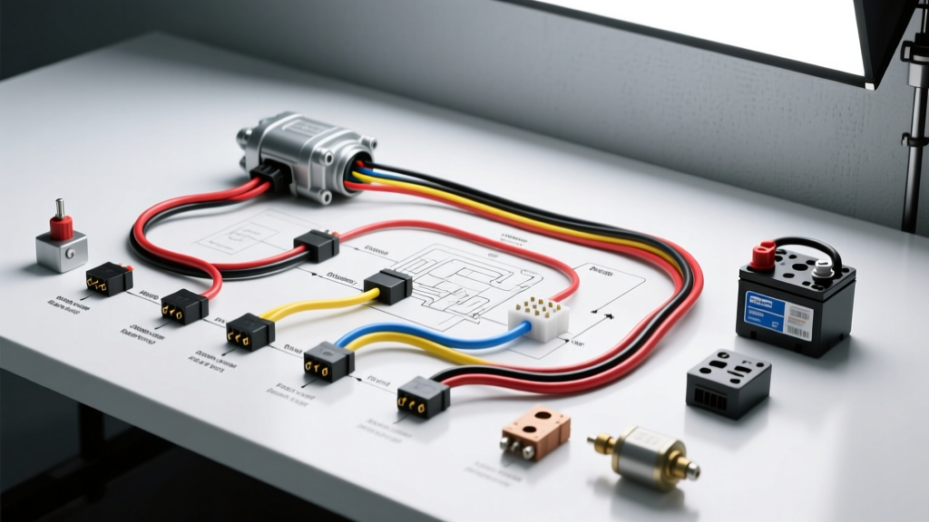
Understanding the F150 Starter Wiring Diagram and Circuit Architecture
Diagnosing a no-crank condition on a 12th-generation (2011-2014) or newer Ford F-150 requires more than just jumping the starter solenoid. The modern Ford EVTM (Electrical and Vacuum Troubleshooting Manual) reveals a complex, network-controlled starter circuit. Unlike older trucks where the ignition switch physically routed 12V power to the starter relay, modern F-150s utilize a Smart Junction Box (SJB), a Transmission Range (TR) sensor, and the Powertrain Control Module (PCM) to authorize engine cranking.
If your F-150 is experiencing a no-crank, no-start issue, or a single loud click without engine rotation, you must follow a logical diagnostic flow. This guide breaks down the F150 starter wiring diagram into a step-by-step troubleshooting sequence, focusing on the Battery Junction Box (BJB) relay, PCM ground drivers, and heavy-gauge power feeds.
F-150 Starter Circuit Specifications & Wire Codes
Before probing connectors, familiarize yourself with the specific wire colors, AWG (American Wire Gauge) sizes, and terminal designations used in the F-150 starter control and power circuits. The following table outlines the standard ISO Mini Starter Relay pinout located in the under-hood BJB.
| Relay Pin | Wire Color (Typical) | AWG Size | Circuit Function & Destination |
|---|---|---|---|
| 30 | Red | 10 AWG | Constant B+ Feed from 175A Mega Fuse |
| 87 | Yellow/Light Green | 14 AWG | Switched Output to Starter Solenoid (S-Terminal) |
| 86 | Light Green/Orange | 18 AWG | Ignition Run/Start Voltage Feed (from SJB/BCM) |
| 85 | White/Violet | 18 AWG | PCM Controlled Ground (Starter Enable) |
Note: Wire colors may vary slightly depending on the exact model year and engine (e.g., 5.0L Coyote vs. 3.5L EcoBoost). Always verify with a vehicle-specific wiring schematic.
Step-by-Step Troubleshooting Flowchart
Follow this diagnostic decision tree to isolate the failure point. You will need a high-quality Digital Multimeter (DMM) capable of measuring DC voltage and resistance, as well as a set of back-probing pins to avoid damaging Motorcraft weather-pack connectors.
Step 1: Verify Main Power and B+ Integrity
The starter motor requires massive current (often exceeding 250 amps during initial cranking). A weak power feed will cause the solenoid to engage but the motor to stall.
- Test Point A: Measure voltage at the Starter Motor B+ terminal (the large stud with the 4 AWG Red wire). You should see battery voltage (12.4V - 12.6V) at all times.
- Test Point B: Inspect the 175A Mega Fuse located in the BJB. A visual inspection is not enough; use your DMM to check for continuity across the fuse test points. Corrosion under the fuse lugs is a common F-150 failure mode.
- Hardware Check: Verify the B+ terminal nut on the starter motor is torqued to 12 Nm (106 lb-in). A loose terminal creates high resistance, leading to heat buildup and melted ring terminals.
Step 2: Test the Starter Control Circuit (Relay & Solenoid)
If the main power is solid, the issue lies in the control circuit. The starter solenoid requires a 12V signal on the S-Terminal to pull the Bendix gear into the flywheel and close the main motor contacts.
- Bypass Test: With the vehicle in Park and the parking brake set, use a jumper wire to apply 12V directly from the battery B+ stud to the starter's S-Terminal (spade connector). If the engine cranks, the starter motor and solenoid are functional. The fault is upstream.
- Relay Coil Feed (Pin 86): Remove the starter relay from the BJB. Turn the ignition to the START position. Probe the female terminal for Pin 86. You should read >10.5V. If 0V, check the ignition switch output and the Smart Junction Box (SJB) fuses.
- Relay Switch Feed (Pin 30): Probe the female terminal for Pin 30. You must read full battery voltage. If missing, the BJB internal bus bar or the feed from the 175A Mega fuse is compromised.
Step 3: Diagnose PCM Interlocks (PATS and TR Sensor)
If Pin 86 has power and Pin 30 has power, but the relay does not click, the PCM is refusing to ground Pin 85. The PCM will inhibit the starter ground for two primary reasons: a security lockout or a missing Park/Neutral signal.
- Check PATS (Passive Anti-Theft System): Look at the theft indicator light on the dashboard. If it is flashing rapidly when the key is turned to START, the PCM does not recognize the transponder chip in the key. The PCM will disable the fuel injectors and the starter relay ground. Try a spare key or check the PATS ring antenna wiring around the ignition cylinder.
- Check the Transmission Range (TR) Sensor: The PCM must see a valid Park or Neutral signal on the CAN bus before authorizing a crank. If the shift linkage is stretched or the TR sensor is misaligned, the PCM thinks the truck is in gear. Turn the key to START, hold it there, and slowly wiggle the shifter between Park and Neutral. If the starter suddenly engages, the TR sensor requires realignment or replacement.
Advanced Voltage Drop Testing for F-150 Starter Circuits
According to SAE International electrical testing standards, a standard test light or a DMM reading static voltage is insufficient for diagnosing high-current cranking circuits. You must perform a dynamic voltage drop test while an assistant holds the key in the START position.
| Test Location | DMM Probes | Maximum Allowable Voltage Drop | Common Failure Mode if Exceeded |
|---|---|---|---|
| Positive Power Side | Battery (+) Post to Starter B+ Stud | 0.50V DC | Corroded battery terminals, frayed 4 AWG cable, or loose Mega fuse lugs. |
| Negative Ground Side | Battery (-) Post to Starter Motor Case | 0.10V DC | Corroded engine block ground strap or paint under the starter mounting bolts. |
| Control Circuit (S-Wire) | Relay Pin 87 Output to Solenoid S-Terminal | 0.20V DC | Corroded BJB relay socket or damaged 14 AWG Yellow/Light Green wire. |
Pro-Tip: Never pierce the insulation of the 14 AWG S-Terminal wire with a test probe. Piercing the wire allows moisture to wick into the copper strands via capillary action, leading to green rot and eventual open-circuit failure months down the road. Always back-probe the connector or test at exposed terminals.
Common F-150 Starter Wiring Failure Modes
Based on field data and dealership service bulletins, the following are the most frequent culprits for F-150 starter wiring failures:
- BJB Water Intrusion: The under-hood Battery Junction Box is prone to seal degradation. Water pools at the bottom of the BJB, corroding the female terminals for Pins 30 and 87. This causes intermittent no-crank conditions, especially in wet weather.
- PCM Ground Driver Failure: The internal transistor in the PCM that grounds Pin 85 can fail due to voltage spikes caused by a failing starter solenoid coil that lacks a functioning flyback diode. Always replace the starter relay if the solenoid is found to be shorted.
- Chafed S-Wire Harness: On 5.0L and 3.5L applications, the wiring harness routing near the exhaust manifold and the rear of the cylinder head can degrade. The Yellow/Light Green 14 AWG wire often melts against the exhaust heat shield, causing a short to ground that blows the ignition feed fuse in the SJB.
Summary
Troubleshooting the F150 starter wiring diagram requires a systematic approach. By verifying the heavy-gauge B+ feeds, testing the ISO relay pins, and understanding the PCM's security and transmission interlocks, you can accurately diagnose any no-crank condition. Always rely on dynamic voltage drop testing rather than static voltage readings to uncover hidden resistance in the F-150's high-current electrical system.