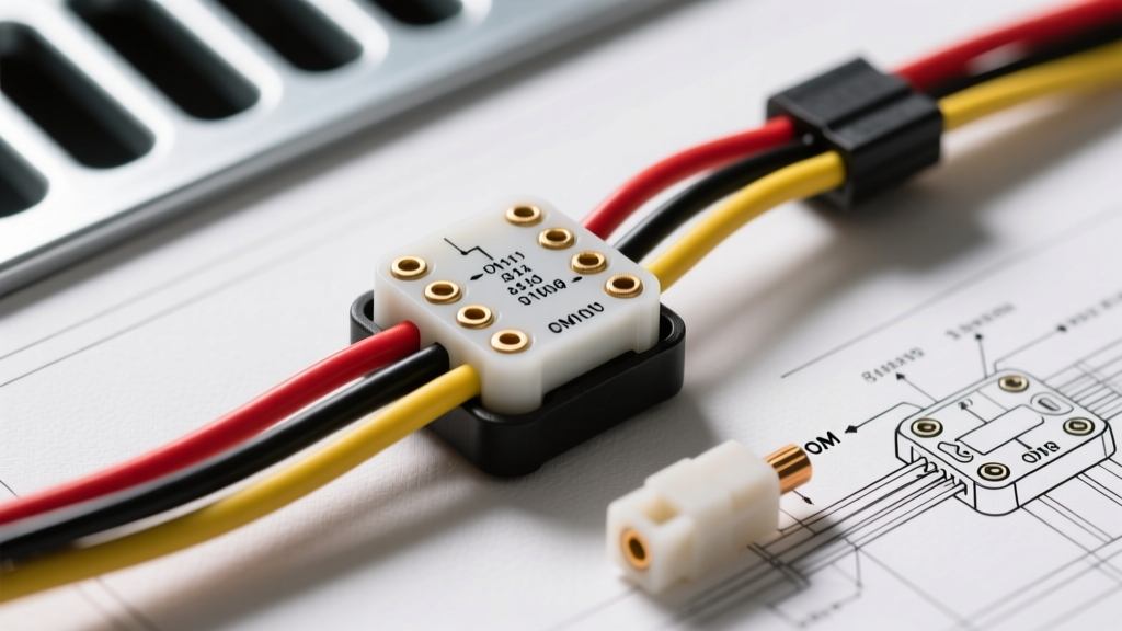
The Engineering Behind the 3 Wire Fuel Sending Unit Wiring Diagram
When diagnosing fuel level inaccuracies, gauge flutter, or persistent diagnostic trouble codes (DTCs) like P0462 or P0463, understanding the underlying circuit topology is critical. Early automotive fuel gauges relied on a simple 1-wire or 2-wire variable resistor (potentiometer) that used the vehicle chassis as the ground return. While cost-effective, this design was highly susceptible to voltage fluctuations caused by varying ground potentials across the vehicle body, leading to erratic gauge behavior. The modern 3 wire fuel sending unit wiring diagram solves this issue by utilizing a dedicated, isolated ground circuit back to the Powertrain Control Module (PCM) or Body Control Module (BCM).
In a 3-wire topology, the fuel level sensor operates as part of a precision voltage divider network monitored by the module's Analog-to-Digital Converter (ADC). The three wires consist of a 5-Volt Reference (VREF), a Signal Return (the wiper output), and a Low-Reference (dedicated sensor ground). This configuration ensures that the PCM reads the exact voltage drop across the resistive card, completely immune to chassis ground noise or high-current draw from nearby fuel pump motors.
Standard OEM Pinout Configuration and Wire Color Codes
While specific wire colors vary by manufacturer (GM, Ford, Chrysler, Toyota), the architectural pinout of the 3-wire fuel level sensor connector remains remarkably consistent across late-model OBD-II vehicles. Below is the standardized reference for the 3-pin Metri-Pack or Micro-Pack connector commonly found on modular fuel pump assemblies.
| Pin | Circuit Function | Typical OEM Wire Color | AWG Size | Signal Type |
|---|---|---|---|---|
| A | 5V Reference (VREF) | Grey / Yellow | 18 AWG | DC Voltage (5.0V) |
| B | Signal Return (Fuel Level) | Yellow / Purple | 18 AWG | Analog DC (0.5V - 4.5V) |
| C | Low-Reference (Sensor Ground) | Black / Black-White | 18 AWG | Ground (< 0.05V Drop) |
Note: Always verify pinouts with a factory service manual, as some manufacturers integrate the low-fuel warning thermistor or fuel pump driver module (FPDM) circuits into the same physical harness bundle, increasing the connector pin count to 4 or 5.
Electrical Specifications and Resistive Card Curves
The heart of the sending unit is the resistive card. Modern units utilize a thick-film cermet (ceramic-metal) composition rather than traditional wire-wound resistors. Cermet cards offer superior resistance to the corrosive effects of sulfur-rich fuel vapors and provide a continuous, infinite-resolution signal without the 'dead spots' common in worn wire-wound units. The PCM supplies a stable 5.0V to one end of the resistive track, while the Low-Reference grounds the other end. The wiper arm, attached to the float lever, sweeps across the track to send a proportional voltage back to the PCM.
Understanding the specific resistance curve for your application is vital for bench-testing a sender before dropping the fuel tank. Different manufacturers utilize opposing sweep directions and resistance values:
| Manufacturer | Empty Resistance | Full Resistance | Approx. Empty Voltage | Approx. Full Voltage |
|---|---|---|---|---|
| General Motors (GM) | 40 Ohms | 250 Ohms | 0.6V | 3.4V |
| Ford Motor Company | 10 Ohms (or 145Ω) | 73 Ohms (or 22Ω) | 0.8V | 2.9V |
| Stellantis (Chrysler) | 0 Ohms | 90 Ohms | 0.2V | 4.2V |
Wire Gauge, Insulation, and Harness Routing Standards
Because the signal return circuit operates on low-voltage analog thresholds (often changing by less than 20 millivolts per gallon of fuel), wire integrity is paramount. The SAE J1128 Low Tension Primary Cable Standard dictates the use of Thin Wall Cross-Linked (TXL) or General Cross-Linked (GXL) insulation for underbody and cabin harnesses. TXL wire offers superior resistance to fuel vapor permeation, heat, and abrasion compared to standard PVC wire.
The standard gauge for the 3-wire sender pigtail is 18 AWG (approximately 0.82 mm²), typically consisting of 19 strands of 30 AWG bare copper. This gauge provides an optimal balance between flexibility (necessary for the float arm's movement) and low circuit resistance. When routing the harness from the fuel pump module flange to the main chassis harness, it is critical to maintain a minimum separation distance of 100mm from high-current ignition wires or the fuel pump power feed (which can draw 10-15 amps and induce electromagnetic interference if unshielded).
Advanced Diagnostic Procedures: Multimeter Verification
Troubleshooting a 3-wire fuel level circuit requires a systematic approach to isolate whether the fault lies in the sensor, the wiring harness, or the control module. Follow this sequence using a high-impedance Digital Multimeter (DMM) capable of measuring millivolts.
Step 1: Verify the 5V Reference (VREF)
Disconnect the fuel sender pigtail and turn the ignition to the 'ON' position (engine off). Set your DMM to DC Volts. Place the positive probe on Pin A (VREF) and the negative probe on a known good engine ground. You should read between 4.90V and 5.10V. A reading of 0V indicates an open circuit to the PCM or a short to ground. A reading below 4.5V suggests excessive resistance in the VREF wire or a failing PCM voltage regulator.
Step 2: The Low-Reference Voltage Drop Test
This is the most overlooked step in fuel gauge diagnostics. A poor ground will skew the signal return voltage, causing the PCM to miscalculate the fuel level. Reconnect the harness and backprobe Pin C (Low-Reference) using a T-pin or breakout box. Place your positive DMM probe on the backprobed Pin C and your negative probe directly on the battery's negative terminal. With the circuit loaded, the voltage drop must be less than 0.050V (50mV). If you read 0.200V or higher, you have corrosion or a loose crimp in the ground circuit, which will artificially inflate the signal return voltage and cause the gauge to read higher than the actual fuel level.
Step 3: Signal Return Sweep and Dropout Analysis
Backprobe Pin B (Signal Return). Have an assistant slowly rock the vehicle side-to-side (or manually move the float arm if the pump is on the bench). Watch the DMM. The voltage should sweep smoothly from the 'Empty' threshold to the 'Full' threshold. Any sudden drops to 0V or spikes to 5V indicate a physical 'dead spot' on the cermet resistive card where the wiper has worn through the conductive layer. According to Delphi Technologies Fuel Pump Module Engineering Guidelines, a single microsecond dropout is enough for the PCM to set a rationality DTC and default the gauge to a safe 'Empty' reading while illuminating the low fuel warning.
Common Failure Modes and Harness Repair Protocols
The most frequent failure point in the 3-wire system is not the resistive card itself, but the connector interface. Fuel tanks are highly pressurized, volatile environments. Over time, microscopic fuel vapors permeate the connector seals. When these sulfur-rich vapors meet the silver or palladium plating on the connector terminals, they form silver sulfide—a black, non-conductive crust that introduces high resistance into the low-voltage signal circuit.
When repairing a damaged 3-wire fuel sender pigtail, never use twist-and-solder methods or standard electrical tape. Solder can wick up the stranded wire via capillary action, creating a rigid section that will fatigue and snap under the constant vibration of the fuel pump assembly. Instead, utilize OEM-style crimp barrels sealed with dual-wall, adhesive-lined polyolefin heat shrink tubing. The inner adhesive layer melts and bonds to the TXL wire insulation, creating a watertight and vapor-tight seal. Furthermore, always pack the connector cavity with a fluorosilicone dielectric grease (such as Nyogel 760A) to displace oxygen and sulfur vapors, preventing future galvanic corrosion on the wiper contacts. For comprehensive wiring repair standards and schematic interpretation, referencing Haynes Automotive Electrical Troubleshooting Manuals is highly recommended for both professional technicians and advanced DIYers.
By adhering to strict voltage drop testing protocols and utilizing proper crimp-and-seal repair techniques, you can permanently resolve erratic fuel gauge behavior and restore the precision of the PCM's fuel level monitoring algorithms.