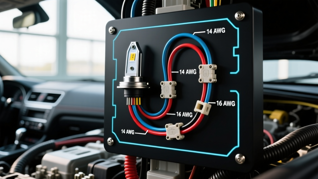
Understanding the 3 Wire Headlight Wiring Diagram
Upgrading your vehicle's lighting system requires a solid understanding of the 3 wire headlight wiring diagram, especially when dealing with standard dual-filament bulbs like the H4, 9003, or 9007. Factory wiring harnesses in older vehicles were typically designed to route the full headlight current directly through the dashboard headlight switch and the multi-function turn signal stalk. This outdated architecture relies on 18 AWG or even 20 AWG primary wire, which creates significant electrical resistance over the long routing path from the battery, through the firewall, to the dash switch, and back out to the engine bay. The result is a severe voltage drop, leading to dim halogen output, prematurely aged bulbs, and in worst-case scenarios, melted plastic headlight switches and severe fire hazards.
To resolve this, automotive electricians utilize a relay-based 3 wire headlight wiring diagram. By introducing standard ISO mini relays into the engine bay, the factory wiring is relegated to a low-current trigger circuit. The heavy electrical load is instead carried by new, thick-gauge wires routed directly from the battery to the headlights. This practical how-to guide provides a comprehensive, step-by-step installation methodology to safely upgrade your vehicle's lighting harness while maintaining OEM-style functionality.
Why Upgrade to a Relay-Based 3-Wire Setup?
According to the principles outlined in AA1CAR's Automotive Lighting Systems guide, halogen headlights require optimal voltage to produce their rated lumen output. A standard 9003/H4 bulb draws approximately 5.08 amps on low beam (55W) and 6.04 amps on high beam (65W) at 13.2 volts. When you factor in the resistance of 20 feet of 18 AWG factory wiring, the voltage reaching the bulb can drop below 11.5 volts. This not only reduces light output by up to 30% but also shifts the color temperature, resulting in a weak, yellowish beam. By implementing a 3 wire headlight wiring diagram with relays, you ensure the bulbs receive a full 13.8 to 14.2 volts directly from the alternator, maximizing visibility and safety.
Essential Components and AWG Specifications
Before beginning the installation, gather the following automotive-grade components. Never use household solid-core wire or cheap vinyl electrical tape; always use stranded, cross-linked polyethylene (XLPE) automotive primary wire and adhesive-lined heat shrink.
| Component | Specification / Size | Application in 3-Wire Diagram | Standard Color Code |
|---|---|---|---|
| Primary Wire (Power/Feed) | 12 AWG or 10 AWG (SGT) | Battery to Relay Pin 30; Relay Pin 87 to Bulb | Red |
| Primary Wire (Ground) | 12 AWG (SGT) | Relay Pin 86 to Chassis; Bulb Ground to Chassis | Black |
| Trigger Wire | 16 AWG or 18 AWG | Factory Headlight Harness to Relay Pin 85 | Yellow (Low), Green (High) |
| Inline Fuse Holder | ATC / ATO (20 Amp) | Main power feed protection near battery | N/A |
| ISO Mini Relay | 12V DC, 40A, 5-Pin (Bosch Style) | Switching high current to the headlights | N/A |
| Headlight Pigtail | H4 / 9003 Ceramic Connector | Termination at the headlight bulb | N/A |
Note: Always adhere to SAE J1128 standards for low-tension primary cable to ensure the wire insulation can withstand under-hood temperatures up to 125°C.
Step-by-Step Installation Guide
Step 1: Safety and Battery Preparation
Disconnect the negative battery terminal using a 10mm or 8mm wrench, depending on your vehicle's battery post size. Clean the battery terminals with a wire brush to ensure optimal conductivity for the new power feeds. Identify a secure mounting location in the engine bay for the relays. They should be mounted away from exhaust headers and moving components like the cooling fan or accessory belts. Use a relay bracket with integrated rubber isolators to prevent vibration-induced internal contact failure.
Step 2: Routing the Main Power Feed
Cut a length of 10 AWG red wire to reach from the positive battery terminal to the relay mounting location, adding 6 inches for slack and routing. Install an inline ATC fuse holder within 6 inches of the battery positive post. Crimp a 3/8-inch ring terminal onto the battery end using a heavy-duty open-barrel crimper, and seal it with dual-wall, adhesive-lined heat shrink. Connect this to the battery positive post. Run the wire to the relay location and terminate it with a female spade connector designed for ISO Pin 30.
Step 3: Establishing the Relay Grounds
Locate a clean, unpainted metal surface on the chassis or inner fender well near the relay mount. Use a 5/16-inch drill bit to create a hole if a factory grounding stud is unavailable. Remove all paint and rust using 80-grit sandpaper. Crimp a ring terminal onto a 12 AWG black wire and secure it to the chassis using a stainless steel bolt, a star washer (to bite into the bare metal), and a nylock nut. Torque to 10 ft-lbs. Connect the other end to ISO Pin 86 on the relay.
Step 4: Splicing the Factory Trigger Wires
Unplug the factory headlight connector. Using a digital multimeter, identify the ground, low beam, and high beam wires by testing for continuity and voltage with the headlights temporarily reconnected and powered. The ground wire will show continuity to the chassis. The other two will show 12V when the respective beam is activated. Cut the factory low and high beam power wires about 3 inches from the original plug. Splice 16 AWG yellow (low) and green (high) trigger wires to the factory harness using solder and heat shrink, or high-quality butt connectors. Route these trigger wires to the relay Pin 85.
Step 5: Running the Output to the Headlights
Run 12 AWG red wire from relay Pin 87 to the new ceramic H4 headlight pigtail. The ceramic material is critical; standard plastic H4 connectors will melt under the heat of a 65W high-beam filament. Crimp female spade terminals onto the output wires and insert them into the ceramic connector housing, ensuring the locking tabs engage. Apply a small amount of dielectric grease to the bulb pins before insertion to prevent galvanic corrosion.
Understanding the ISO Relay Pinout Configuration
Correctly wiring the 5-pin ISO mini relay is the core of the 3 wire headlight wiring diagram. While the 5th pin (87a) is typically unused in headlight applications, understanding the internal coil and switch mechanics is vital for troubleshooting.
| Pin Number | Function | Connection Target | Wire Gauge |
|---|---|---|---|
| 85 | Coil Trigger (+12V from switch) | Factory Low/High Beam Wire | 16 AWG |
| 86 | Coil Ground | Vehicle Chassis Ground | 12 AWG |
| 30 | Common Power Input (+12V) | Battery Positive (via Fuse) | 10 AWG |
| 87 | Normally Open Output | Headlight Bulb Power Feed | 12 AWG |
| 87a | Normally Closed (Unused) | Cap and insulate | N/A |
Troubleshooting Common Wiring Faults
Even with a perfect 3 wire headlight wiring diagram, real-world vehicle quirks can cause issues. Below is a diagnostic decision tree for common post-installation problems.
- Symptom: Both Low and High Beams turn on simultaneously when the high beam switch is engaged, or lights flicker.
- Cause: High beam indicator backfeed. In many classic GM, Ford, and Toyota vehicles, the dashboard high-beam indicator bulb is wired in series or parallel with the high beam trigger wire. When relays are added, current flows backward through the indicator bulb and into the low beam relay trigger circuit.
- Fix: Install a 1N4001 blocking diode on the high beam trigger wire (between the factory harness splice and relay Pin 85). The silver band on the diode must face toward the relay to allow current flow to the relay coil while blocking reverse backfeed.
- Symptom: Headlights are still dim, or one side is noticeably brighter than the other.
- Cause: Poor chassis grounding or voltage drop on the new 12 AWG ground wire.
- Fix: Perform a voltage drop test. Set your multimeter to DC Volts. Place the red probe on the battery negative post and the black probe on the headlight bulb's ground pin while the lights are on. A reading above 0.1V indicates excessive resistance. Remove the ground ring terminal, sand the chassis to bare metal, and re-secure with a star washer.
- Symptom: Relays click rapidly or chatter when the switch is turned on.
- Cause: Undersized trigger wires or excessive voltage drop in the factory headlight switch causing the relay coil to receive less than 9V (the minimum pull-in voltage for most 12V ISO relays).
- Fix: Verify the factory headlight switch contacts are clean. If the factory wiring is too degraded, run a new 14 AWG trigger wire directly from a switched ignition source through a new dashboard toggle switch to feed the relay coils.
Final Inspection and Testing
Once all connections are terminated, sealed with adhesive heat shrink, and secured with split-loom tubing and zip ties, reconnect the battery. Turn on the low beams and verify that the relays click audibly and the voltage at the headlight pigtail reads within 0.2V of the battery voltage. Cycle the high beams and ensure the dashboard indicator functions correctly without backfeeding. By strictly following this 3 wire headlight wiring diagram and utilizing heavy-gauge, automotive-spec materials, you will achieve maximum lumen output, eliminate dashboard switch overheating, and ensure long-term electrical reliability.