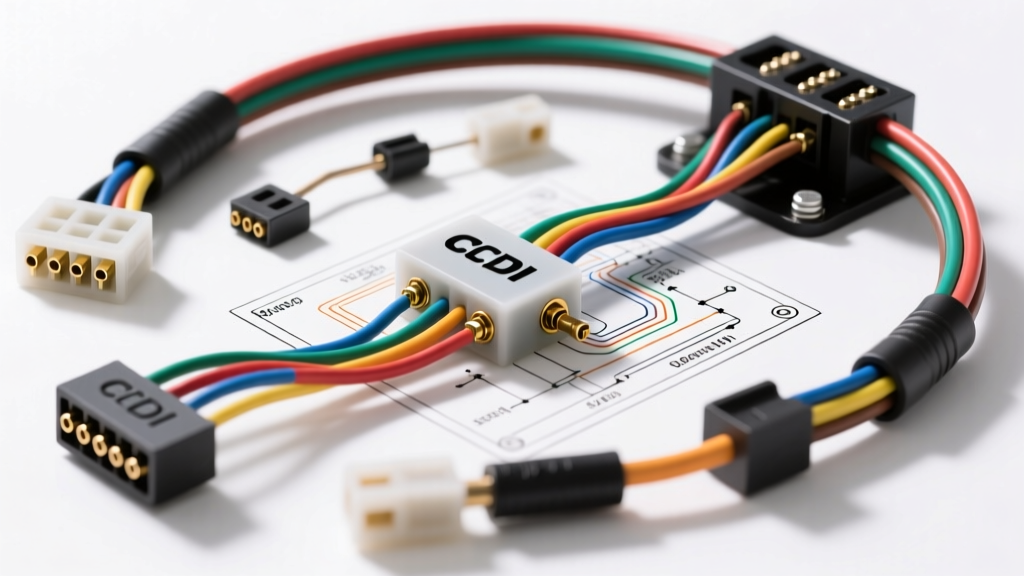
Introduction to the 8-Pin CDI Ignition System
When diagnosing a no-spark condition on small displacement motorcycles, ATVs, dirt bikes, and scooters, referencing an accurate CDI ignition 8 pin CDI wiring diagram is the critical first step. The Capacitor Discharge Ignition (CDI) box acts as the brain of your engine's spark delivery system. It stores electrical energy from the stator or battery and releases it in a high-voltage microsecond burst to the ignition coil exactly when the piston reaches the correct timing position.
Unlike modern fuel-injected ECUs, 8-pin CDI units are largely analog, relying on discrete thyristors, capacitors, and resistors. Because they operate in high-vibration, high-heat environments, wiring harness degradation, connector corrosion, and stator failures are common. This guide provides a comprehensive, step-by-step troubleshooting flow to isolate faults within the 8-pin CDI circuit using a standard digital multimeter (DMM) and a peak voltage adapter.
Standard 8-Pin CDI Connector Pinout Reference
While exact wire colors can vary slightly between manufacturers (e.g., Honda, Yamaha, and GY6 clone engines), the functional layout of the 8-pin Molex-style or JST weatherproof connector remains remarkably consistent. Below is the industry-standard pinout configuration for a typical AC/DC hybrid 8-pin CDI unit.
| Pin | Function | Typical Wire Color | AWG Size | Signal Type |
|---|---|---|---|---|
| 1 | AC Power In (Stator Lighting Coil) | Yellow or Pink | 14-16 AWG | AC Voltage (30-90V) |
| 2 | Chassis Ground | Green or Black | 16 AWG | DC Ground (0V) |
| 3 | Ignition Coil Trigger Output | Black/Yellow | 18 AWG | High-Voltage DC Pulse |
| 4 | Pulse Pickup Coil (+) | Blue/White | 18-20 AWG | AC Signal (0.5-4V Peak) |
| 5 | Pulse Pickup Coil (-) | Green/White | 18-20 AWG | Signal Ground |
| 6 | Kill Switch / Magneto Ground | Black/White | 16 AWG | DC Ground (When Active) |
| 7 | DC Battery Power OR Tachometer | Red (DC) or Black (Tach) | 16 AWG | 12V DC or Pulse |
| 8 | Rev Limiter / Secondary Trigger | Varies (Often Unused) | 18 AWG | Switched Ground |
Critical Warning: AC-CDI vs. DC-CDI Identification
Before beginning your diagnostic flow, you must identify whether your specific 8-pin unit is an AC-CDI or a DC-CDI. Plugging a DC-CDI into an AC wiring harness (or vice versa) will instantly destroy the internal capacitor and voltage regulator diodes.
- AC-CDI: Derives all operating power from the stator's dedicated lighting/ignition coil (Pin 1). Pin 7 is typically unused or routed to a tachometer. These units are generally smaller in physical size.
- DC-CDI: Derives operating power from the vehicle's 12V battery via the key switch (Pin 7 is Red). Pin 1 may be unused or used for a secondary timing map. These units are usually physically larger to house heavier step-up transformer coils.
Step-by-Step CDI Ignition Troubleshooting Flow
Follow this sequential diagnostic tree to isolate the root cause of your no-spark or misfire condition. Always begin with a fully charged battery (minimum 12.6V DC) and clean the main chassis ground strap before testing.
Step 1: Verify Stator and Lighting Coil AC Voltage
If the CDI does not receive adequate primary voltage, it cannot charge its internal capacitor. Set your multimeter to AC Volts (VAC).
- Disconnect the 8-pin CDI connector.
- Probe Pin 1 (Yellow/Pink wire) and Pin 2 (Ground) on the harness side (stator side) of the connector.
- Crank the engine or kick-start vigorously.
- Expected Result: You should read between 30V and 90V AC depending on cranking RPM. If the voltage is below 20V AC, the stator ignition source coil is failing, or the air gap between the flywheel magnets and stator core is excessive (spec is typically 0.010" - 0.020").
Step 2: Test the Pulse Pickup Coil (Trigger)
The pickup coil tells the CDI exactly when to fire. A failing pickup coil is the most common cause of intermittent spark loss when the engine reaches operating temperature.
- Set your multimeter to Ohms (Ω).
- Probe Pin 4 (Blue/White) and Pin 5 (Green/White) on the harness side.
- Static Resistance Test: The reading should be between 100Ω and 180Ω at room temperature. An open circuit (OL) indicates a broken internal winding. A reading below 80Ω indicates shorted windings.
- Dynamic Peak Voltage Test: For absolute certainty, connect a peak voltage adapter to your DMM. Probe the pickup wires while cranking. You must see a minimum of 0.5V to 1.5V peak. According to Electrosport Industries, a weak magnetic field from a cracked flywheel woodruff key can also mimic a failing pickup coil by altering the timing gap.
Step 3: Check the Kill Switch and Ground Circuit
The kill switch operates on a "ground-to-kill" logic. If the kill switch wire is frayed and touching the frame, the CDI will perpetually think the key is off.
- Set the multimeter to Continuity mode.
- Probe Pin 6 (Black/White) and a known good chassis ground.
- With the key ON and the kill switch in the RUN position, there should be NO continuity (OL).
- With the key OFF or the kill switch engaged, there SHOULD be continuity (near 0.0Ω).
- If continuity exists while the bike is in the RUN position, trace the Black/White wire back through the handlebar switch cluster. Look for pinched wires near the steering stem or corroded contacts inside the switch housing.
Step 4: Measure Ignition Coil Primary and Secondary Resistance
If the CDI is receiving power, seeing a trigger signal, and not being grounded by the kill switch, the fault likely lies in the ignition coil or spark plug cap.
- Disconnect the primary wire (Black/Yellow) from the ignition coil.
- Measure Primary Resistance: Place one probe on the primary terminal and the other on the coil mounting bracket (ground). Expected reading: 0.1Ω to 0.5Ω.
- Measure Secondary Resistance: Remove the spark plug cap. Place one probe inside the high-tension lead hole and the other on the primary terminal. Expected reading: 3,000Ω to 5,000Ω (3k-5kΩ). Note: If your spark plug cap contains an internal resistor (typically 5kΩ), you must add this to your expected secondary reading.
Common Failure Modes & Wiring Repair Best Practices
When repairing the wiring harness leading to your 8-pin CDI, never use twist-on wire nuts or standard electrical tape. The engine bay environment is subjected to severe thermal cycling and fuel vapors, which will degrade adhesive tape and corrode bare copper within weeks.
- Wire Selection: Always replace damaged harness wires with cross-linked polyethylene (XLPE) insulated wire that meets SAE J1128 specifications for low-tension primary cable. Use 16 AWG for power and ground circuits (Pins 1, 2, 6, 7) to minimize voltage drop, and 18 AWG for signal wires (Pins 3, 4, 5).
- Connector Repair: If the 8-pin Molex connector is brittle or pins are backed out, replace it with a marine-grade, injection-molded weatherproof connector. Apply a dab of dielectric grease to the pins before mating to prevent galvanic corrosion and moisture ingress.
- Soldering vs. Crimping: For in-harness splices, use adhesive-lined marine heat shrink butt connectors crimped with a ratcheting crimper. Soldering can create a rigid joint that is prone to fatigue cracking under high engine vibration, a phenomenon well-documented in Clymer and Haynes motorcycle service manuals.
Summary
Diagnosing an 8-pin CDI system requires a methodical approach. By verifying stator AC output, validating the pickup coil's resistance and peak voltage, confirming the kill switch logic, and testing the ignition coil, you can accurately pinpoint the failure without resorting to the expensive and inefficient method of "parts swapping." Keep your multimeter handy, reference the pinout table, and ensure your wiring repairs meet automotive electrical standards for long-term reliability.