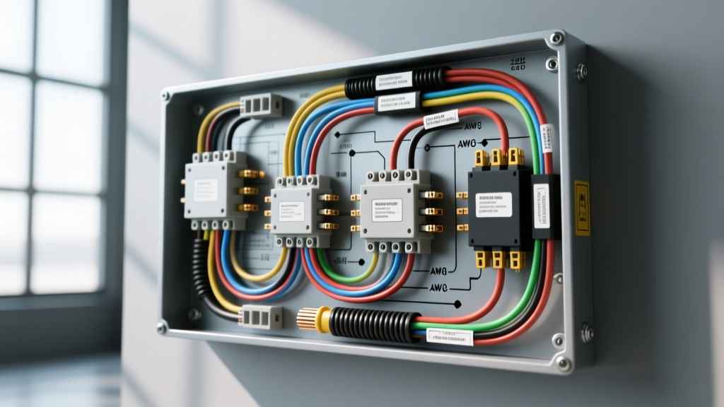
Overcoming Factory PDC Limitations with an Auxiliary Sub Panel
Modern heavy-duty trucks, such as the Ford Super Duty and RAM 2500/3500 series, utilize highly integrated Power Distribution Centers (PDCs) managed by the Body Control Module (BCM). While these OEM PDCs are excellent for factory loads, they are entirely unsuited for high-draw aftermarket accessories like off-road LED light bars, winch solenoids, onboard air compressors, or auxiliary fuel transfer pumps. Tapping directly into OEM wiring or overloading factory fuse slots risks blowing surface-mount fuses, melting factory harnesses, or triggering CAN-bus load-shedding faults that disable critical vehicle systems.
The professional solution is installing an automotive auxiliary sub panel. In the context of vehicle wiring diagrams, a 'sub panel' refers to a centralized, secondary power distribution block and relay center that operates independently of the BCM while utilizing the vehicle's main battery bank. This complete wiring diagram for sub panel integration provides a comprehensive walkthrough for routing main power, configuring ISO relays, establishing robust ground planes, and protecting sensitive vehicle electronics from voltage spikes.
Sub Panel Architecture and Component Selection
A properly engineered automotive sub panel consists of three primary subsystems: the main overcurrent protection feed, the heavy-duty busbar distribution block, and the relay control matrix. Unlike residential sub panels that deal with 120/240V AC power, an automotive sub panel manages 12V/24V DC high-amperage loads, meaning that resistance and voltage drop are your primary enemies.
Busbar and Overcurrent Protection
The core of your sub panel should be a tin-plated copper busbar rated for at least 250A continuous duty. The busbar must feature M8 or M10 stainless steel studs. When terminating 4 AWG or 2 AWG ring terminals on these studs, it is critical to use Belleville washers (conical spring washers). These washers maintain constant tension on the terminal joint during the severe thermal cycling and vibration inherent to heavy-duty truck operation. The recommended torque spec for M8 brass nuts on a copper busbar is exactly 10-12 Nm; overtightening will strip the threads or cause copper cold-flow, while undertightening leads to micro-arcing and localized melting.
Complete Wiring Diagram for Sub Panel: Step-by-Step Walkthrough
Step 1: Main Power Feed Routing
The main feed connects the vehicle's battery positive terminal to the sub panel's input busbar. For a standard accessory sub panel handling up to 120A of combined continuous load, use 4 AWG SAE J1128 cross-linked polyethylene (XLPE) insulated cable. XLPE insulation is mandatory for engine bay routing due to its superior resistance to heat, oil, and abrasion compared to standard PVC wire.
Overcurrent protection must be installed within 7 inches of the battery positive terminal. A 150A ANL fuse or Mega fuse is ideal here. This main fuse protects the 4 AWG feed wire in the event of a catastrophic short to ground before the wire reaches the sub panel's internal branch fuses.
Step 2: Establishing a True Ground Plane
A common failure point in custom truck wiring is relying on the chassis frame for the sub panel's main ground. Modern truck frames are often painted, powder-coated, or treated with anti-corrosion chemicals that act as dielectric insulators. To ensure a flawless ground plane, run a dedicated 4 AWG ground wire directly from the sub panel's negative busbar to a verified OEM engine block ground point or directly to the battery negative terminal. Terminate the ground ring terminal with a star washer to bite through any surface oxidation on the mounting point, and coat the finished joint in dielectric grease to prevent galvanic corrosion.
Step 3: Relay Coil Control and Flyback Protection
The sub panel will utilize standard Bosch-style 5-pin ISO Mini relays to switch high-amperage loads. When wiring the relay coil control circuit (Pins 85 and 86) to an OEM Upfitter switch or a CAN-bus compatible toggle switch, you must account for inductive kickback. When the relay coil is de-energized, the collapsing magnetic field generates a high-voltage reverse spike that can instantly destroy the BCM or the Upfitter switch module.
To prevent this, solder a 1N4001 flyback diode across the relay coil wires (Pins 85 and 86), with the diode's cathode (the silver stripe) pointing toward the 12V+ switched trigger source. This diode safely recirculates the voltage spike back through the coil, protecting your truck's expensive multiplexed control modules.
Wire Color Codes and AWG Specification Chart
Adhering to standardized wire colors and AWG sizes ensures that your wiring diagram for sub panel integration remains serviceable for future diagnostics. The following chart outlines the specifications for a standard 4-relay auxiliary lighting and compressor sub panel.
| Circuit Function | AWG Size | Wire Color Code | Max Continuous Load | Branch Fuse Type | Terminal Type |
|---|---|---|---|---|---|
| Main Battery Feed (+) | 4 AWG | Red (XLPE) | 120A | 150A ANL | 3/8" Ring (Heat Shrink) |
| Main Ground (-) | 4 AWG | Black (XLPE) | 120A | N/A | 3/8" Ring w/ Star Washer |
| Relay Coil Trigger (+) | 16 AWG | Yellow/Blue Stripe | 2A | 5A ATO | 1/4" Spade (Nylon Insulated) |
| Relay Coil Ground (-) | 16 AWG | Black/White Stripe | 2A | N/A | 1/4" Spade (Nylon Insulated) |
| Relay Load Feed (Pin 30) | 10 AWG | Red | 30A | 20A-30A ATO | 1/4" Male Spade |
| Accessory Load Out (Pin 87) | 12 AWG | Blue | 20A | Fused at Source | Weather-Pack / Deutsch DT |
Advanced Troubleshooting: Voltage Drop and Parasitic Draw
Even with a perfect wiring diagram for sub panel execution, environmental factors and poor crimps can degrade performance over time. The most accurate way to diagnose sub panel health is through Voltage Drop Testing under load.
A healthy 12V DC circuit should never experience more than a 3% voltage drop, which equates to a maximum loss of 0.36V across the entire circuit. To test the positive feed, set your Digital Multimeter (DMM) to DC Volts. Place the red probe directly on the battery positive post and the black probe on the sub panel's input busbar stud. Turn on your highest-draw accessory (e.g., a 40-inch LED light bar). If the DMM reads higher than 0.36V, you have excessive resistance in the main feed, usually caused by a failing ANL fuse element, a loose battery clamp, or undersized wire.
For Parasitic Draw Testing, disconnect the main 4 AWG feed from the battery and place your DMM (set to 10A Amps) in series between the battery post and the feed wire. With all relays disengaged and the truck asleep, the sub panel should draw exactly 0.00A. Any reading above 0.02A indicates a shorted relay coil, a melted branch fuse holder, or moisture ingress causing a high-resistance short to ground inside the sub panel enclosure.
Environmental Sealing and Vibration Mitigation
Heavy-duty trucks operate in environments characterized by extreme moisture, road salt, and high-frequency vibration. Standard PVC electrical tape is strictly prohibited in professional sub panel builds, as it unspools under heat and traps moisture against the copper.
Instead, all sub panel terminations must utilize adhesive-lined, dual-wall marine heat shrink with a 3:1 shrink ratio. When heated, the inner layer of polyamide adhesive melts and flows into the wire strands, creating a waterproof seal that prevents capillary action from wicking moisture up the wire jacket. For connections exposed to direct water spray, encapsulate the relay spade terminals in Raychem DR-25 heat shrink tubing or use sealed Deutsch DT connectors for all accessory load outputs.
Authoritative References
The specifications and methodologies outlined in this walkthrough are derived from industry-standard automotive and commercial vehicle electrical guidelines:
- SAE J1128: Low Tension Primary Cable Standard - Defines the thermal, chemical, and mechanical requirements for XLPE and PVC insulated automotive wire used in sub panel feeds.
- Littelfuse Automotive & Commercial Vehicle Catalog - Provides the time-current characteristic curves for ANL and Mega fuses essential for sizing main sub panel overcurrent protection.
- Blue Sea Systems: Circuit Calculation for Boat and RV - Offers the definitive formulas for calculating DC voltage drop and selecting appropriate AWG sizes for 12V/24V auxiliary distribution panels.