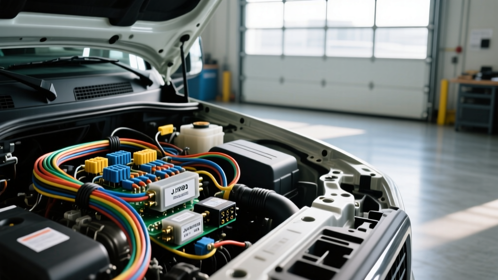
The Hidden Dangers of a 'Volvo Truck Wiring Diagrams Free Download'
When technicians and owner-operators search for a volvo truck wiring diagrams free download, they are often met with a myriad of unverified, low-resolution, or heavily modified PDF schematics. While the temptation to bypass expensive OEM service portal subscriptions is understandable, relying on these free resources for Class 8 heavy-duty vehicles—such as the Volvo VNL, VHD, or VAH series equipped with D11 or D13 engines—introduces catastrophic risks. Modern Volvo trucks utilize complex multiplexed J1939 CAN bus networks, sensitive Vehicle Engine Control Units (VECU), and precise emissions harnesses. A single misinterpreted wire color code or outdated pinout from a generic free download can result in fried logic boards, stranded freight, and severe safety hazards.
This guide outlines the most critical mistakes made when using unverified Volvo schematics and provides authoritative safety protocols for troubleshooting heavy-duty electrical systems.
5 Fatal Mistakes Made Using Unverified Volvo Schematics
1. Misidentifying J1939 CAN Bus Pins on the EECU
The most common failure point when using outdated free diagrams is misidentifying the Society of Automotive Engineers (SAE) J1939 Controller Area Network (CAN) pins. Free diagrams often fail to differentiate between the primary chassis CAN bus and the private engine CAN bus. On a Volvo D13 engine, the Engine ECU (EECU) relies on specific twisted-pair wiring for data transmission. According to SAE International J1939 Standards, CAN High (CAN-H) is typically Yellow and CAN Low (CAN-L) is Green. However, OEM chassis builders sometimes alter harness colors for secondary networks. Relying on a generic color chart instead of verifying the physical EECU connector (often a 70-pin or 120-pin Deutsch HD10 series) with a breakout box can lead to cross-wiring the 5V reference signal into the data link, instantly destroying the EECU.
2. Ignoring GHG Emissions Harness Variations
A free wiring diagram downloaded from a third-party forum might be labeled 'Volvo VNL D13,' but fail to specify the Greenhouse Gas (GHG) emissions generation. The wiring architecture for a GHG14 (pre-2017) engine differs vastly from a GHG17 (2017+) or GHG20 (2021+) engine. Later models incorporate complex Selective Catalytic Reduction (SCR) dosing modules, DEF tank heaters, and NOx sensor networks. Using a GHG14 schematic to troubleshoot a GHG17 DEF doser circuit will result in misdiagnosing the pulse-width modulated (PWM) signals, leading to unnecessary replacement of $1,500 aftertreatment components.
3. Overlooking Ground Splice Pack (GSP) Corrosion Points
Unverified diagrams rarely include the physical routing and location of Volvo's Ground Splice Packs (GSP). Volvo utilizes specific GSP nodes (e.g., GSP-4 near the battery box or GSP-2 behind the dash) to consolidate chassis grounds. A common mistake is testing continuity to the negative battery terminal instead of the specific GSP node. Furthermore, techs often fail to inspect these packs for copper oxidation (verdigris), which causes high-resistance voltage drops that mimic failed sensors.
4. Backprobing Weather-Sealed Connectors Incorrectly
Free PDF guides rarely emphasize proper connector maintenance. Volvo heavy-duty trucks use Deutsch DT, DTM, and Weather-Pack connectors sealed with silicone grommets. Technicians following basic online guides often use standard paperclips or oversized test light probes to 'backprobe' these connectors. This permanently deforms the terminal seals, allowing moisture ingress. Within months, the capillary action draws water into the EECU or VECU harness, causing internal module corrosion.
5. Overloading the VECU with Aftermarket Accessories
Owner-operators frequently use free wiring diagrams to locate 'switched power' sources for aftermarket LED light bars or CB radios. Tapping directly into the VECU's low-current driver circuits (which are often limited to 2A or 5A) to power high-draw accessories will melt the internal VECU traces. Proper protocol dictates using the VECU signal wire to trigger a heavy-duty 40A Bosch-style relay, powered directly from the battery distribution block with an inline AGU fuse.
Volvo VNL 9-Pin Diagnostic & EECU J1939 Pinout Reference
Below is an OEM-verified reference table for the standard 9-pin diagnostic connector (Amphenol/Deutsch) and the corresponding J1939 data link. Always verify with a Digital Multimeter (DMM) before piercing wires or backprobing.
| Connector / Pin | Function / Network | Standard Wire Color | Voltage / Resistance Spec |
|---|---|---|---|
| 9-Pin: Pin C | J1939 CAN High (Chassis) | Yellow | 2.5V - 3.5V (Idle) |
| 9-Pin: Pin D | J1939 CAN Low (Chassis) | Green | 1.5V - 2.5V (Idle) |
| 9-Pin: Pin A | Chassis Ground | Black / White | < 0.1V Drop to Battery (-) |
| 9-Pin: Pin B | Unswitched Battery Power | Red | 12.2V - 14.4V |
| 9-Pin: Pin F | J1587 Data Link | Blue / White | ~5V (Legacy Protocol) |
| EECU: Term 13/14 | Private Engine CAN Bus | Yellow / Green (Varies) | 60 Ohms (Network Total) |
Note: The J1939 CAN bus requires exactly two 120-ohm terminating resistors in the circuit. Measuring across Pin C and Pin D with the batteries disconnected should yield exactly 60 ohms. If a free diagram fails to show the location of these resistors (usually housed in the dash cluster and the EECU), troubleshooting network drops becomes a guessing game.
Critical Safety Protocols for Volvo Heavy-Duty Electrical Work
Never Use a Test Light on Multiplexed Networks
A traditional incandescent test light draws significant amperage (often 2A to 5A) to illuminate the bulb. Probing a J1939 CAN-H or CAN-L circuit with a test light will instantly overload the EECU's internal transceiver chip, shorting the entire network and shutting down the truck's powertrain. Always use a high-impedance Digital Multimeter (DMM) with a minimum 10-megohm input impedance, or a dedicated automotive oscilloscope to read CAN bus waveforms.
Airbag and SRS System Precautions
Modern Volvo VNL cabs are equipped with Supplemental Restraint Systems (SRS). The wiring harnesses for these systems are universally wrapped in yellow loom. Free wiring diagrams rarely include the mandatory SRS safety procedures. Before performing any continuity testing near the steering column, dash, or seatbelt pretensioners, you must disconnect the main battery isolator switch and wait a minimum of 15 minutes for the SRS backup capacitors to discharge. Backprobing an SRS circuit with a DMM's internal 9V battery can inadvertently deploy the airbag.
Perform Voltage Drop Testing, Not Just Continuity
The Technology & Maintenance Council (TMC) emphasizes that a wire showing 'continuity' (0 ohms) on a multimeter can still be entirely useless if it is corroded or frayed internally. A single strand of 12 AWG wire will show continuity but will suffer massive voltage drop under the 40A load of an engine cooling fan motor. Always perform dynamic voltage drop testing across the circuit while it is under load. A healthy Volvo heavy-duty ground circuit should exhibit less than 0.10V drop under full load.
Sourcing Authoritative Volvo Wiring Schematics
To avoid the severe financial and safety risks associated with a generic volvo truck wiring diagrams free download, professionals must utilize verified resources:
- Volvo Premium Tech Tool (PTT): The OEM diagnostic software includes live, build-specific wiring diagrams tied directly to the truck's chassis VIN, ensuring you are viewing the exact harness configuration that left the New River Valley plant.
- SAE J1939 Documentation: For understanding the foundational logic of the CAN bus networks, refer directly to the SAE J1939 Digital Annex.
- Volvo Trucks North America Service Portal: Authorized service portals provide updated Technical Service Bulletins (TSBs) that often include revised wiring schematics addressing known factory harness chafing or routing defects.
Electrical diagnostics on Class 8 Volvo trucks requires precision, patience, and verified data. Bypassing OEM resources for free internet downloads is a gamble where the house always wins, and your truck's ECU always loses.