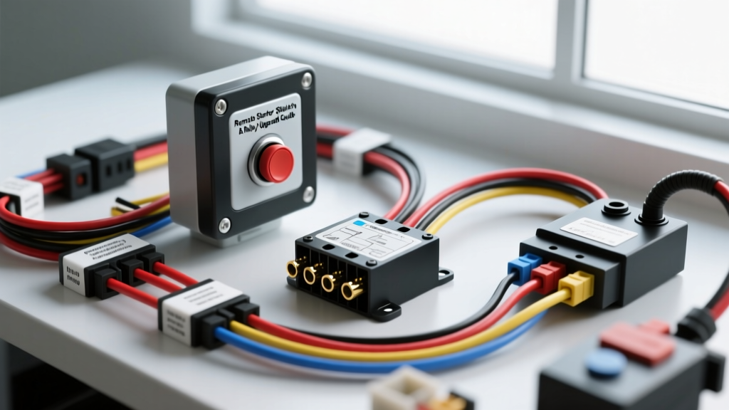
Introduction to Remote Starter Switch Modifications
Adding a remote starter switch is one of the most valuable upgrade and modification projects for custom hot rods, race cars, and off-road builds. Whether you are breaking in a new flat-tappet camshaft, performing rolling engine diagnostics, bleeding a clutch hydraulic system, or operating a front-mounted winch, a remote starter switch allows you to crank the engine safely from outside the driver's seat. However, a proper remote starter switch wiring diagram is critical. Many DIY builders make the mistake of wiring a momentary push-button switch directly to the starter solenoid, leading to melted switches, voltage drops, and severe fire hazards. This guide provides an expert-level, relay-integrated wiring schematic designed for high-amperage automotive applications, ensuring your modification is both functional and safe.
Why Direct Solenoid Wiring is a Critical Mistake
The starter solenoid's 'S' (Start) terminal requires a significant inrush current to pull the heavy copper contact disc and engage the starter motor gear with the flexplate. Depending on the vehicle and solenoid type (e.g., GM Delco, Ford 3-post, or modern gear-reduction mini-starters), the 'S' terminal can draw between 15 and 35 amps during the initial engagement phase.
Standard aftermarket momentary push-button switches are typically rated for 10 to 15 amps continuous. Wiring a standard switch directly to the solenoid will cause the internal contacts to arc, pit, and eventually weld shut or melt the plastic housing. By integrating a standard 4-pin, 30-amp Bosch-style automotive relay into your remote starter switch wiring diagram, the push-button only handles the low-amperage control circuit (less than 1 amp), while the relay's heavy-duty contacts handle the high-amperage solenoid load. This drastically increases the lifespan of your switch and ensures full battery voltage reaches the starter solenoid.
Component Selection and Wire Gauge Specifications
When executing this modification, adhering to SAE J1128 Low Tension Primary Cable standards is essential for fire prevention and voltage efficiency. Below is the required bill of materials and wire gauge specification chart for a standard 12V V8 application.
| Component / Circuit | AWG Size | Wire Color | Specification / Notes |
|---|---|---|---|
| Battery to Relay (Pin 30) | 10 AWG | Red | Must be fused within 18 inches of the battery positive terminal. |
| Relay to Solenoid 'S' (Pin 87) | 10 AWG | Blue | Routes to the starter solenoid start spade terminal. |
| Relay Coil Ground (Pin 85) | 14 AWG | Black | Routes through the Neutral Safety Switch (NSS) to chassis ground. |
| Switch to Relay Coil (Pin 86) | 14 AWG | Yellow | Trigger wire from the momentary push-button switch. |
| Battery to Push-Button | 14 AWG | Red | Fused with a 5A inline ATC fuse for control circuit protection. |
Step-by-Step Remote Starter Switch Wiring Diagram Guide
Follow these precise routing and termination steps to build a reliable remote cranking system. For further reference on factory starter circuit logic, consult AutoShop 101 Starter Circuit Diagnostics to understand how your specific OEM solenoid operates.
Step 1: Battery and Fuse Integration
Begin by disconnecting the negative battery cable. Cut a length of 10 AWG red wire. Crimp a 5/16-inch ring terminal on one end and attach it to the battery positive post. Within 18 inches of this connection, splice in a 30-amp ATC inline fuse holder. This fuse is non-negotiable; it protects the 10 AWG power feed from shorting against the chassis and causing an electrical fire. Route this wire to the engine bay location where you plan to mount the relay.
Step 2: Wiring the 4-Pin Automotive Relay
Mount a standard 4-pin SPST (Single Pole, Single Throw) relay in a dry, protected area of the engine bay.
- Pin 30 (Common): Connect the fused 10 AWG red wire from the battery.
- Pin 87 (Normally Open): Crimp a 10 AWG blue wire with the appropriate spade connector for your starter solenoid (usually a 1/4-inch female quick-disconnect). Route this wire down to the starter solenoid's 'S' terminal.
Step 3: Integrating the Neutral Safety Switch (NSS)
Safety is paramount in any remote starter switch wiring diagram. If the vehicle is left in gear, pressing the remote button will cause the car to lurch forward or backward, potentially causing severe injury. You must integrate the factory Neutral Safety Switch (or clutch interlock switch) into the control circuit.
We recommend switching the ground side of the relay. Connect a 14 AWG black wire to Pin 85 on the relay. Route this wire to the output side of your Neutral Safety Switch. The input side of the NSS should be grounded to a clean, bare-metal chassis point. This ensures the relay will only energize when the transmission is in Park or Neutral.
Step 4: Connecting the Momentary Push-Button
Run a 14 AWG red wire from a switched 12V source or directly from the battery (with a 5A inline fuse) to one terminal of your momentary push-button switch. Run a 14 AWG yellow wire from the second switch terminal to Pin 86 on the relay. When the button is pressed, 12V flows through the yellow wire, energizing the relay coil, which closes the heavy-duty contact between Pin 30 and Pin 87, sending cranking amps to the starter.
The Ignition 'I' Terminal Bypass Challenge
A common failure mode in custom remote start setups occurs when the engine cranks but refuses to fire. This is usually traced back to the ignition system's ballast resistor or resistance wire. In classic Ford 3-post solenoids and older GM points-style ignitions, the 'I' terminal on the solenoid sends a full 12V bypass to the ignition coil only during the crank cycle.
If you are using a remote starter switch with the ignition key left in the 'ON' position (rather than the 'START' position), the coil receives reduced voltage through the ballast resistor, which is insufficient to fire the spark plugs under heavy cranking voltage drops. To solve this, your remote starter switch wiring diagram must include an ignition bypass relay. Wire a secondary relay triggered by the same yellow switch wire (Pin 86 parallel feed) to send 12V directly to the coil positive terminal while the button is depressed. For comprehensive chassis wiring solutions, review Painless Performance Wiring Manuals for pre-engineered ignition bypass modules.
Troubleshooting Common Wiring Faults
Use this diagnostic decision tree if your remote starter switch fails to operate correctly after installation:
- Symptom: Relay clicks, but starter does not engage.
Cause: Voltage drop across Pin 30 or Pin 87, or undersized wire.
Fix: Verify 10 AWG wire is used. Check for loose crimps or corrosion at the battery ring terminal and solenoid spade. Perform a voltage drop test across the relay contacts while pressing the button. - Symptom: Push-button gets hot or melts.
Cause: Switch is wired directly to the solenoid 'S' terminal, bypassing the relay.
Fix: Immediately disconnect the battery. Rewire the switch to handle only the low-amperage relay coil trigger (Pin 86). - Symptom: Starter engages, but engine will not start or dies when button is released.
Cause: Ignition coil is not receiving full 12V during cranking due to ballast resistor voltage drop.
Fix: Ensure the ignition key is held in the 'START' position while pressing the remote button, or install an ignition bypass relay as detailed above. - Symptom: Remote switch does nothing; no relay click.
Cause: Open circuit in the Neutral Safety Switch ground path or blown 5A control fuse.
Fix: Bypass the NSS temporarily with a jumper wire to isolate the fault. Check the 5A inline fuse on the push-button power feed.
Safety Protocols and Termination Best Practices
Engine bays are harsh environments characterized by extreme heat, vibration, and exposure to hydrocarbons. Never use standard electrical tape to insulate your crimps; the adhesive will melt, and the tape will unravel. Always use adhesive-lined, dual-wall heat shrink tubing on all ring and spade terminals. The inner adhesive layer melts and seals the wire strands, preventing moisture ingress and copper oxidation. Furthermore, ensure all wiring is secured with UV-resistant zip ties and routed away from exhaust manifolds and moving steering linkages. By adhering to this remote starter switch wiring diagram and utilizing the correct AWG specifications, your upgrade project will provide years of reliable, safe engine cranking.