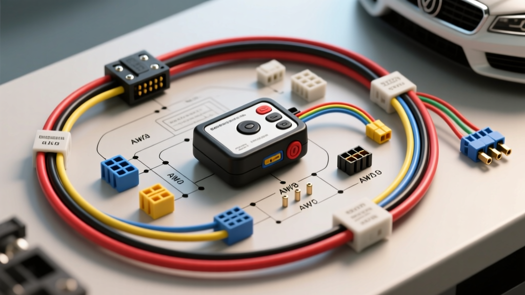
Introduction to Aftermarket Alarm Integration
Integrating an aftermarket security system with a vehicle's factory door locks requires a precise understanding of electrical circuits, pulse logic, and relay switching. Whether you are working on a classic vehicle with discrete wiring or a modern platform utilizing multiplexed networks, interpreting the central locking car alarm system wiring diagram is the most critical step in the installation process. A flawed connection can lead to blown transistors, parasitic battery drains, or complete failure of the vehicle's body control module (BCM). This comprehensive installation guide breaks down the schematic requirements, wire gauge specifications, and relay logic necessary to execute a professional-grade alarm and central locking integration.
Decoding the Central Locking Car Alarm System Wiring Diagram
The typical central locking car alarm system wiring diagram is divided into three primary harnesses: the main power harness, the sensor input harness, and the auxiliary output harness. Understanding the color codes and signal types for each is mandatory before stripping a single wire.
Main Power and Ground Harness
The main harness supplies the high-current demands of the alarm brain and the siren. You will typically find a heavy-gauge RED wire for 12V constant battery power and a BLACK wire for the chassis ground. According to Mobile Electronics Certification Program (MECP) standards, these wires must never be spliced into factory low-gauge circuits. They require direct connections to the battery or main distribution block using appropriate over-current protection.
Sensor and Trigger Inputs
The input harness monitors the vehicle's perimeter. Key wires include the door trigger inputs (usually GREEN for negative triggers and H1/BLUE for positive triggers), the hood pin switch input, and the brake pedal input. Modern alarms also include a tachometer sense wire and a foot brake wire to enable passive arming and automatic door locking features.
Door Trigger Inputs and Diode Isolation
One of the most common mistakes when following a central locking car alarm system wiring diagram is improperly interfacing the door trigger circuits. In many vehicles, the door jamb switches share a common circuit with the interior dome light. If you connect the alarm's negative door trigger input directly to this shared circuit without isolation, the 12V positive current from the dome light will backfeed into the alarm module the moment the door opens, instantly destroying the internal micro-transistor.
To prevent this, you must utilize diode isolation. Solder a 1N4001 or 1N4004 rectifier diode in-line with the door trigger wire. The cathode (indicated by the silver band) must point toward the alarm module's input wire, while the anode connects to the vehicle's door switch wire. This creates a one-way electrical valve, allowing the negative ground signal to reach the alarm while blocking any positive voltage backfeed from the dome light circuit.
Central Locking Actuator Logic Types
The lock and unlock outputs on your alarm module are typically low-current negative pulses. However, factory central locking systems operate on various logic types. You must identify the vehicle's logic type to wire the interface relays correctly.
- Type A (Positive Pulse): The factory switch sends a direct 12V positive pulse to the lock actuators. Requires a standard relay to convert the alarm's negative output into a positive pulse.
- Type B (Negative Pulse): The factory switch sends a direct ground pulse to the lock actuators. The alarm's negative outputs can often be connected directly, provided the current draw does not exceed the module's internal relay rating (usually 500mA).
- Type C (Multiplex / Resistor Network): Common in modern Chrysler, Ford, and GM vehicles. The lock and unlock signals are sent over a single wire using varying resistance values. You cannot use standard relays; a digital multiplex interface module is required to decode and inject the correct resistor values.
- Type D (Alternating Polarity / Polarity Reversal): Common in older European vehicles and some Japanese trucks. The factory uses two wires that alternate between 12V and Ground to reverse the motor direction. This requires a complex two-relay setup per function to safely reverse polarity without creating a dead short.
Step-by-Step Installation Procedure
- Disconnect the Battery: Always remove the negative battery terminal before beginning any automotive electrical work to prevent short circuits and airbag deployment.
- Establish Power and Ground: Route the 10 AWG RED main power wire to the battery positive terminal, ensuring an inline 15A fuse is placed within 18 inches of the battery. Secure the 10 AWG BLACK ground wire to a clean, unpainted metal surface on the chassis using a ring terminal and a self-tapping screw or factory bolt.
- Interface the Ignition and Accessories: Connect the alarm's YELLOW ignition wire and RED/WHITE accessory wire to the corresponding circuits at the ignition switch harness. Verify these circuits with a multimeter to ensure they drop to 0V when the key is removed.
- Wire the Door Triggers: Locate the door switch wires in the kick panel or A-pillar. Test with a multimeter to confirm if they trigger via ground (negative) or 12V (positive). Install your 1N4004 isolation diodes if necessary, and solder the connections. Avoid using T-taps, which cause voltage drop and wire corrosion over time.
- Configure the Lock/Unlock Relays: If the vehicle uses Type A (Positive Pulse) locking, wire two standard Bosch ISO mini relays. Connect Pin 86 to the alarm's negative lock/unlock outputs. Connect Pin 85 to a 12V constant source. Connect Pin 30 to a 12V constant source via a 10A fuse. Connect Pin 87 to the vehicle's factory lock/unlock wires. Leave Pin 87a empty and taped back.
- Test and Secure: Reconnect the battery. Test the perimeter sensors, shock sensor, and lock/unlock outputs before zip-tying the module and wrapping the harnesses in automotive-grade Tesa tape to prevent rattles.
Wire Gauge and Relay Specification Chart
Adhering to SAE J1128 standards for low tension primary cable ensures that the wiring can handle the thermal and electrical loads without melting or causing excessive voltage drop. Refer to the chart below for exact specifications.
| Circuit Function | Wire Color (Typical) | Required AWG | Connection Method |
|---|---|---|---|
| 12V Constant Power | Red | 10 - 12 AWG | Ring Terminal to Battery / Fused |
| Chassis Ground | Black | 10 - 12 AWG | Ring Terminal to Bare Metal |
| Ignition / Accessory | Yellow / Red-White | 18 AWG | Solder and Heat Shrink |
| Door Triggers | Green / H1-Blue | 18 AWG | Solder with 1N4004 Diode |
| Lock/Unlock Outputs | Blue-Green / Blue-White | 16 AWG (Relay Feed) | Bosch Relay Pins 86 / 85 |
| Siren Output | Brown | 14 AWG | Direct to Siren Positive |
Advanced Troubleshooting and Multimeter Testing
Even with a perfect central locking car alarm system wiring diagram reference, installation errors occur. If the alarm arms but the doors fail to lock, the issue is almost always in the relay interface. Use a digital multimeter (DMM) set to DC Volts to troubleshoot.
First, verify that the alarm module is actually sending the ground pulse. Place your DMM's black lead on a known good ground and the red lead on the alarm's blue-green lock output wire. Press the lock button on the remote. The DMM should briefly drop from 12V down to near 0V for roughly 0.8 seconds. If it does not, the module's internal output is blown.
If the pulse is present, move to the relay. Check for 12V at Pin 30 and 12V at Pin 85. If both are present, but the relay does not click when the alarm triggers, the relay coil is faulty or the ground path from Pin 86 to the alarm module is broken. According to Bosch Automotive Mobility Solutions, a standard ISO mini relay coil requires approximately 150mA to energize. Ensure your wiring can support this current without resistance caused by poor crimps.
Finally, if the doors lock but immediately unlock, or exhibit erratic behavior, you are likely dealing with a double-pulse issue or a multiplex network conflict. In vehicles with CAN bus networks, injecting raw 12V pulses can confuse the BCM. In these cases, abandon the analog relay method and install a digital data interface module that communicates with the vehicle's OBD2 network via high-speed CAN H and CAN L wires.
Authoritative References
- Mobile Electronics Certification Program (MECP) - Best practices for automotive security installations and wire management.
- SAE International J1128 - Specifications for low tension primary automotive cable and AWG ratings.
- Bosch Automotive Relay Specifications - Pinout logic and current ratings for ISO mini and micro relays.