Mastering the Allison Transmission Wiring Diagram: A Step-by-Step Troubleshooting Flow
When diagnosing shift complaints, limp-mode conditions, or diagnostic trouble codes (DTCs) like P0751, P0756, or P0973 in GM Duramax and medium-duty commercial trucks, the electrical system is frequently the true culprit. The Allison 1000 and 2000 series transmissions rely on a complex network of pulse-width modulated (PWM) solenoids and discrete shift valves to command gear changes. Misinterpreting a mechanical failure when the root cause is a chafed 18 AWG wire, a corroded Transmission Control Module (TCM) pin, or a failing internal case connector can lead to thousands of dollars in unnecessary rebuilds. This guide provides a systematic, step-by-step troubleshooting flow utilizing the official Allison transmission wiring diagram to isolate and repair electrical faults with absolute precision.
Essential Diagnostic Tools & Safety Protocols
Before consulting the schematic, ensure you have the correct diagnostic equipment. Standard automotive multimeters are often insufficient for modern transmission diagnostics due to the high-frequency switching of PWM solenoids.
- Digital Multimeter (DMM): Must have a minimum 10-megohm input impedance to prevent damaging sensitive TCM driver circuits during resistance testing.
- Automotive Oscilloscope: Required for verifying PWM duty cycles on the Main Pressure Control and Torque Converter Clutch (TCC) circuits.
- Breakout Box / Harness Jumper: Essential for back-probing the 80-way external TCM connector without spreading the terminal pins.
- Pin Tension Tester: To verify female terminal grip on the external harness connectors.
- Dielectric Grease: Specifically formulated for high-temperature transmission fluid environments (e.g., Nyogel 760G or equivalent).
Safety Warning: Always disconnect the negative battery cable and wait a minimum of 60 seconds for the TCM capacitors to discharge before unplugging the main transmission harness to prevent voltage spikes that can fry the internal driver transistors.
Step 1: External TCM Connector Inspection
The majority of Allison 1000 electrical faults originate at the external TCM connector before they ever reach the transmission pan. Depending on the generation (Gen 4 vs. Gen 5), the TCM utilizes a high-density 80-way or dual-connector setup. According to the Allison Transmission Service Information Portal, environmental sealing failures here are a primary cause of intermittent limp-mode events.
- Visual Inspection: Disconnect the main harness. Inspect the weather-pack seals for tearing or flattening. Look for green or white crusty corrosion on the male and female pins, which indicates capillary action drawing moisture into the connector.
- Pin Spread Check: Use a pin tension tool on the female harness side. If the tool slides in without noticeable drag, the terminal must be replaced. A loose pin on the CAN High/CAN Low circuit (typically Pins 14 and 15 on Gen 4) will cause U-code communication faults and immediate transmission defaults.
- Chafing Check: Inspect the first 12 inches of the harness loom exiting the connector. On GM HD trucks, this harness often rubs against the bellhousing or transmission case, wearing through the 16 AWG TXL insulation and shorting the 12V ignition feed to ground.
Step 2: Navigating the Allison Transmission Wiring Diagram
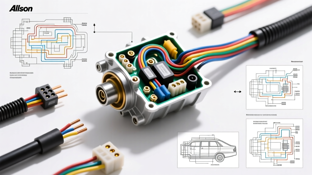
Reading an Allison schematic requires understanding the division between the external chassis harness and the internal transmission harness. The external diagram will show the TCM power feeds (typically fused B+ and Ignition feeds using 14 AWG or 12 AWG red/pink wires), the J1939 CAN bus network, and the routing to the external case connector. The internal diagram details the 7-way case connector and the color-coded 18 AWG PTFE (Teflon) insulated wires that route directly to the valve body solenoids. PTFE insulation is mandatory here, as standard cross-linked polyethylene (XLPE) will degrade rapidly when submerged in hot Dexron VI or TES 295 transmission fluid.
Step 3: Internal Harness & Case Connector Decision Tree
If the external harness and TCM pins test clean, the fault likely lies within the transmission pan. Drop the pan, remove the filter, and expose the internal 7-way case connector. Use the following decision tree to trace DTCs based on the wiring diagram.
- IF DTC P0751 (Shift Solenoid A Performance) or P0973 (Solenoid A Circuit Low) is present:
- Step A: Measure resistance across internal 7-way Pin 1 (Solenoid A) and the common ground.
- IF resistance is 10-14 ohms: The internal solenoid and harness are intact. The issue is likely a mechanical valve body bind or an external TCM driver fault.
- IF resistance is OL (Open) or < 5 ohms: The internal 18 AWG brown wire is broken, or the solenoid coil has shorted internally. Replace the internal harness or solenoid block.
- Step B: Inspect the 7-way case connector plastic housing for cracks. The retaining bolts must be torqued to exactly 10 Nm (89 lb-in). Over-torquing cracks the bakelite housing, allowing fluid to short the pins.
- Step A: Measure resistance across internal 7-way Pin 1 (Solenoid A) and the common ground.
- IF DTC P0741 (TCC Stuck Off) is present:
- Step A: Test internal 7-way Pin 6 (TCC PWM Solenoid). Expected resistance is 4.0 - 6.0 ohms.
- IF resistance is out of spec: Replace the TCC solenoid.
- IF resistance is normal: Connect an oscilloscope to the external TCM TCC control wire. Verify the PWM signal sweeps from 10% to 90% duty cycle. If the signal is present but the TCC does not apply, suspect a mechanical leak in the turbine shaft seals or a failed TCC control valve.
- Step A: Test internal 7-way Pin 6 (TCC PWM Solenoid). Expected resistance is 4.0 - 6.0 ohms.
Allison 1000 Internal 7-Way Solenoid Specification Chart
The following table outlines the standard internal case connector pinout, wire colors, and resistance specifications at 20°C (68°F). Always cross-reference your specific serial number with the OEM Allison transmission wiring diagram, as harness revisions can occasionally alter wire jacket colors.
| Pin | Component | Internal Wire Color | Resistance (@ 20°C) | Signal Type |
|---|---|---|---|---|
| 1 | Shift Solenoid A | Brown | 10.0 - 14.0 Ω | On/Off (12V) |
| 2 | Shift Solenoid B | Orange | 10.0 - 14.0 Ω | On/Off (12V) |
| 3 | Shift Solenoid C | Yellow | 10.0 - 14.0 Ω | On/Off (12V) |
| 4 | Shift Solenoid D | Green | 10.0 - 14.0 Ω | On/Off (12V) |
| 5 | Shift Solenoid E | Blue | 10.0 - 14.0 Ω | On/Off (12V) |
| 6 | TCC PWM Solenoid | Red | 4.0 - 6.0 Ω | PWM (Variable) |
| 7 | Main Pressure Control | Black/White | 4.0 - 6.0 Ω | PWM (Variable) |
Step 4: Shift Solenoid & Pressure Control Circuit Verification
When the wiring diagram indicates a PWM-controlled circuit (Pins 6 and 7), a standard multimeter will only tell you if the coil is intact, not if it is functioning dynamically. The SAE J1939 Standard for heavy-duty vehicle networks dictates precise communication and actuation parameters. To properly verify the Main Pressure Control solenoid, connect an oscilloscope to the control wire at the TCM breakout box.
With the engine running in Park, the TCM typically commands a high line pressure (low duty cycle, approx. 10-20%). As you shift into Drive, the duty cycle should smoothly transition to modulate pressure based on engine torque and turbine speed. If the oscilloscope reveals a flat 12V line or a noisy, degraded square wave, the TCM's internal current-control driver has likely failed due to thermal fatigue. Conversely, if the scope shows a perfect PWM wave but the transmission exhibits harsh shifts or flares, the mechanical pressure regulator valve in the valve body is sticking, and the electrical system is completely absolved.
Common Failure Modes & Expert Fixes
- Fluid Intrusion via Capillary Action: If the external harness is damaged or the drip loop is eliminated during a previous repair, transmission fluid can wick up through the wire strands inside the insulation directly into the TCM. Fix: Always ensure a proper drip loop exists in the harness before securing it to the chassis. If fluid is found in the TCM, the TCM must be replaced and the entire external harness flushed or replaced, as the fluid cannot be reliably cleaned from inside the wire insulation.
- Internal Harness Chafing: The internal 18 AWG wires routing from the 7-way connector to the solenoid block are secured by plastic looms and zip ties. Over time, vibration causes these wires to rub against the aluminum valve body casting, wearing through the PTFE coating and causing intermittent short-to-ground codes (e.g., P0974, P0977). Fix: Inspect the entire length of the internal harness. Wrap any areas near sharp casting edges in high-temperature Teflon tape or replace the internal harness assembly entirely. Never use standard vinyl electrical tape inside the transmission pan.
- Ground Strap Corrosion: The TCM relies on a dedicated chassis ground, usually located near the passenger side cylinder head or frame rail on GM applications. A corroded ground will cause back-feeding through the CAN bus, resulting in phantom solenoid codes. Fix: Remove the ground bolt, clean the mating surface to bare metal with a wire brush, apply a thin layer of anti-oxidant paste, and torque to 25 Nm.
Authoritative References
- Allison Transmission Official Service Information & Manuals Portal - For generation-specific TCM pinouts, torque specifications, and internal harness routing diagrams.
- SAE International J1939 Standard Documentation - For understanding heavy-duty CAN bus network topologies and TCM communication fault isolation.
- AA1CAR Automotive Transmission Electrical Diagnostics - For foundational oscilloscope PWM testing procedures and solenoid driver circuit analysis.