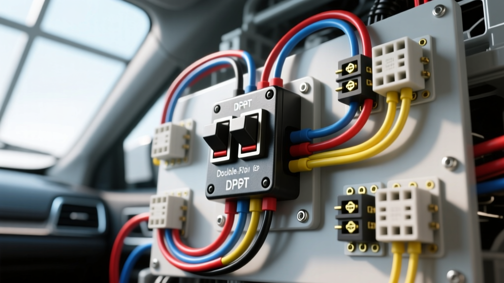
Introduction to DPDT Switches in Automotive Applications
In the realm of custom automotive electrical systems, few components offer the versatility of the Double Pole Double Throw (DPDT) toggle switch. Whether you are wiring a winch polarity reversal, a dual-battery isolation circuit, or a linear actuator for a custom air suspension setup, understanding the correct topology is essential. A DPDT switch is essentially two separate Single Pole Double Throw (SPDT) switches actuated by a single physical lever. This allows you to control two independent circuits simultaneously or manipulate a single circuit's polarity.
Finding a precise wiring diagram double pole double throw toggle switch schematic can be confusing due to the six-terminal configuration. Unlike standard ON-OFF-ON rocker switches, toggle switches often lack printed terminal numbers on the casing, requiring a multimeter to identify the common poles. This guide breaks down terminal identification, provides a definitive polarity-reversal wiring schematic, and compares the top DPDT switch models for harsh automotive and off-road environments.
Decoding the Terminals: Pinout and Identification
A standard maintained DPDT toggle switch features six spade terminals arranged in two columns of three. To properly wire the switch, you must first identify the "Common" terminals (the center pins in each column). Using a digital multimeter set to continuity mode, you can map the internal contacts.
| Terminal Position | Left Column (Pole 1) | Right Column (Pole 2) | Switch State (Up) | Switch State (Down) |
|---|---|---|---|---|
| Top | Pin 1 | Pin 4 | Connected to Common | Open |
| Middle (Common) | Pin 2 | Pin 5 | N/A | N/A |
| Bottom | Pin 3 | Pin 6 | Open | Connected to Common |
Note: Terminal numbering can vary slightly by manufacturer (e.g., Carling vs. Cole Hersee), but the physical center-row commons remain universal. Always verify with a multimeter before applying 12V power.
The Definitive Polarity Reversal Wiring Diagram
The most common and complex automotive application for a DPDT switch is DC motor polarity reversal. This is used for power windows, winch in/out controls, and hydraulic dump bed actuators. By creating an "X" cross-jumper pattern on the switch terminals, you can reverse the positive and negative feeds to the load without requiring a specialized relay block.
Step-by-Step Polarity Reversal Wiring
- Power In: Connect your switched +12V source to Pin 2 (Left Common).
- Ground In: Connect your chassis ground to Pin 5 (Right Common).
- The "X" Jumpers: Install a jumper wire from Pin 1 to Pin 6. Install a second jumper wire from Pin 3 to Pin 4.
- Load Out: Connect Motor Wire A to Pin 1 (which is jumpered to 6). Connect Motor Wire B to Pin 4 (which is jumpered to 3).
Circuit Logic Trace
- Switch UP: Pin 2 (+12V) connects to Pin 1 (Motor Wire A). Pin 5 (Ground) connects to Pin 4 (Motor Wire B). The motor runs Forward.
- Switch DOWN: Pin 2 (+12V) connects to Pin 3, which is jumpered to Pin 4 (Motor Wire B). Pin 5 (Ground) connects to Pin 6, which is jumpered to Pin 1 (Motor Wire A). The motor runs Reverse.
Expert Tip: When wiring inductive loads like winch motors or linear actuators, always install a flyback diode across the motor terminals to suppress inductive kickback, which can arc and melt the internal copper contacts of the toggle switch.
Product Comparison: Selecting the Right DPDT Switch
Not all toggle switches are built to survive the under-hood environment or the vibration of an off-road chassis. Below is a comparison of three distinct DPDT switch categories commonly used in custom vehicle builds.
| Feature | Cole Hersee 58312 Series | Carling 2D521-N (V-Series) | Nilight/Baosity Illuminated |
|---|---|---|---|
| Best Application | Heavy-Duty Winch / PTO | Marine / External Roof Racks | Interior Auxiliary Lighting |
| Amperage Rating | 25A @ 12V DC | 20A @ 12V DC | 20A @ 12V DC |
| Ingress Protection | IP65 (Dust/Splash Resistant) | IP68 (Fully Submersible) | IP54 (Interior Use Only) |
| Terminal Type | 1/4" (6.35mm) Spade | 1/4" (6.35mm) Spade | 1/4" Spade + LED Ground Pin |
| Actuator Style | Maintained (ON-ON) | Maintained (ON-ON) | Maintained w/ Neon/LED Indicator |
1. Heavy-Duty Maintained (Cole Hersee 58312-A)
The Cole Hersee 58312 series is the industry standard for commercial trucks and heavy off-road rigs. Featuring a robust brass casing and silver-plated copper contacts, it handles high inrush currents (up to 25A continuous) without carbon tracking. The IP65 rating makes it suitable for under-hood auxiliary fan overrides or PTO (Power Take-Off) engagement, provided it is shielded from direct high-pressure power washing.
2. IP68 Waterproof Sealed (Carling 2D521-N)
For external mounting on roof racks, boat dashboards, or exposed bumper winch controls, the Carling V-Series sealed toggles are mandatory. These feature an internal silicone boot and O-ring gaskets that prevent moisture intrusion. According to Littelfuse/Carling engineering specs, these switches can withstand salt spray and complete submersion, preventing the internal corrosion that plagues standard switches in winter-weather climates.
3. Illuminated DPDT (Nilight / Generic LED)
Illuminated DPDT toggles feature a seventh terminal dedicated to grounding the internal LED indicator. While visually appealing for interior switch panels, they are prone to failure in high-vibration environments. Furthermore, the internal LED resistor can sometimes cause "backfeeding" in sensitive PCM/ECU circuits if not isolated with a blocking diode. Restrict these to interior lighting bars and low-draw accessory circuits.
Wire Sizing and Connector Selection Standards
A common failure point in custom DPDT wiring is the use of undersized wire or cheap vinyl-insulated crimp connectors. Automotive environments require adherence to SAE J1128 standards for low-tension primary cable. GXL or TXL cross-linked polyethylene (XLPE) wire is highly recommended due to its thin insulation profile and high heat resistance (up to 150°C), which is critical when routing wires near exhaust headers or engine blocks.
| Switch Amperage Rating | Max Continuous Load | Recommended Wire Gauge (AWG) | Connector Specification |
|---|---|---|---|
| 15A DPDT | 12A | 14 AWG GXL | 1/4" Nylon Fully Insulated Spade |
| 20A DPDT | 16A | 12 AWG GXL | 1/4" Heat-Shrink Avikrimp Spade |
| 25A DPDT | 20A+ | 10 AWG GXL | 1/4" Heavy-Duty Brass Spade |
Pro-Tip on Crimping: Never use solder on toggle switch spade terminals. The heat from soldering can melt the internal phenolic resin separator inside the switch housing, leading to an internal short circuit. Always use a high-quality ratcheting crimper (such as the Knoweasy or Titan ratcheting crimpers) to ensure a gas-tight mechanical connection.
Troubleshooting Common DPDT Wiring Failures
If your DPDT circuit is malfunctioning, use this diagnostic decision tree to isolate the fault:
- Symptom: Switch works in one direction, but trips the main fuse in the other.
Cause: A miswired polarity reversal "X" jumper. You have likely connected a +12V common directly to a Ground common on the same throw. Verify the cross-jumpers (1-to-6 and 3-to-4) are isolated from the power inputs. - Symptom: Motor stutters or operates at half-speed.
Cause: Voltage drop across carbon-tracked switch contacts. Heavy inductive loads create micro-arcing when the switch is toggled, burning the copper. Replace the switch with a higher amperage rating or use the DPDT switch solely to trigger a heavy-duty 100A continuous-duty solenoid. - Symptom: Illuminated LED stays on dimly even when the switch is OFF.
Cause: Induced voltage or backfeeding from a shared ground bus. Install a 1N4001 rectifier diode in-line with the LED ground wire to force one-way current flow.
Authoritative References
For further reading on automotive switch topologies and wire ampacity derating in high-temperature engine bays, consult the following resources: