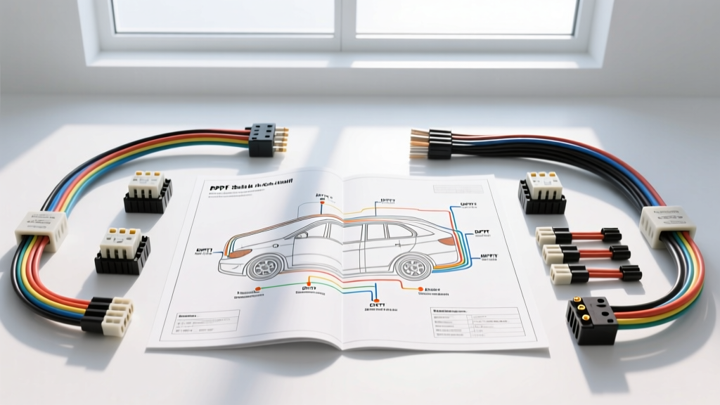
Understanding the Hand-Off-Auto (HOA) Circuit Architecture
When automotive enthusiasts and professional fabricators search for a hand off auto switch wiring diagram pdf, they are typically attempting to integrate high-draw auxiliary systems—such as dual radiator cooling fans, auxiliary fuel lift pumps, or onboard air compressors—into a vehicle's existing electrical network. The core engineering challenge in these setups is achieving a manual override ('Hand') without damaging the vehicle's ECU, PCM, or thermal sensors via electrical backfeed.
A standard Single Pole Double Throw (SPDT) toggle switch is fundamentally flawed for this application. If you tie the manual 12V feed and the ECU-controlled 'Auto' feed together on a single pole, switching to manual mode will send 12V backward through the thermal switch or directly into the PCM's low-side driver transistor, often resulting in catastrophic silicon failure. To solve this, professional automotive electrical schematics utilize a Double Pole Double Throw (DPDT) switch configured in a Hand-Off-Auto (HOA) layout. This guide provides a complete, expert-level walkthrough of the DPDT HOA wiring architecture, ensuring safe isolation and reliable operation.
Component Bill of Materials and Wire Specifications
Adhering to SAE J1128 standards for low-tension primary automotive cable is critical to prevent voltage drop and thermal runaway. The following table outlines the required materials for a dual auxiliary cooling fan setup drawing approximately 35 amps combined.
| Component / Wire | Specification | AWG | Color Code | Circuit Function |
|---|---|---|---|---|
| Main Power Feed | SAE J1128 Cross-Linked | 10 AWG | Red | Battery (+) to Relay Pins 30 |
| Load Feed | SAE J1128 Cross-Linked | 10 AWG | White | Relay Pins 87 to Fan Motors |
| Auto Trigger Feed | Standard Primary Wire | 16 AWG | Blue | Thermal Switch / ECU to DPDT Pins 1 & 4 |
| Manual Trigger Feed | Standard Primary Wire | 16 AWG | Yellow | Fused Ignition 12V to DPDT Pins 3 & 6 |
| Switch Output | Standard Primary Wire | 16 AWG | Green | DPDT Pins 2 & 5 to Relay Pins 86 |
| Ground Circuit | Standard Primary Wire | 12 AWG | Black | Fan Motors & Relay Pins 85 to Chassis |
| Toggle Switch | DPDT ON-OFF-ON, 20A rated | N/A | N/A | Isolates Auto and Manual control feeds |
| Relays (x2) | ISO 7588-1 Bosch-Style 4-Pin | N/A | N/A | 30A/40A switching for high-current loads |
DPDT Switch Pinout Configuration
The secret to a safe HOA circuit lies in the physical isolation provided by the DPDT switch. A standard DPDT toggle features six terminals on the rear housing, divided into two independent poles. By assigning one pole to the Auto circuit and the second pole to the Manual circuit, we guarantee that the ECU trigger wire and the manual battery feed never make electrical contact.
| Terminal Number | Pole Assignment | Connection Target | Switch Position Active |
|---|---|---|---|
| Terminal 1 | Pole 1 (Top) | Auto Trigger (Thermal/ECU) | UP (Auto) |
| Terminal 2 | Pole 1 (Center) | Output to Relay 1 (Pin 86) | Common (Always connected to 1 or 3) |
| Terminal 3 | Pole 1 (Bottom) | Manual Trigger (Fused 12V) | DOWN (Hand) |
| Terminal 4 | Pole 2 (Top) | Auto Trigger (Thermal/ECU) | UP (Auto) |
| Terminal 5 | Pole 2 (Center) | Output to Relay 2 (Pin 86) | Common (Always connected to 4 or 6) |
| Terminal 6 | Pole 2 (Bottom) | Manual Trigger (Fused 12V) | DOWN (Hand) |
Step-by-Step Wiring Walkthrough
Phase 1: High-Current Load and Relay Power
Begin by routing the 10 AWG Red wire from the vehicle's main battery distribution block to the engine bay. Install a 40A MIDI or Mega fuse within 18 inches of the battery positive terminal to protect against dead shorts. Split this main feed to supply both Relay 1 and Relay 2 at Pin 30. Use adhesive-lined heat shrink ring terminals (3/8-inch stud) and torque the connections to the relay harness to 12-15 in-lbs to prevent vibration-induced loosening. Route the 10 AWG White wires from Pin 87 on each relay directly to the auxiliary fan motors. Ensure all high-current ground paths utilize dedicated chassis grounding points, sanded down to bare metal, rather than relying on shared factory grounds which can cause ground-loop voltage drops.
Phase 2: Control Circuit and DPDT Isolation
Mount the DPDT switch in the cabin or a protected under-hood switch panel. Run the 16 AWG Blue wire from your thermal switch (or ECU auxiliary fan driver) to Terminals 1 and 4 on the switch. Run the 16 AWG Yellow wire from a switched ignition source (protected by a 5A Mini-ATO fuse) to Terminals 3 and 6. Finally, run the 16 AWG Green output wires from the center terminals (2 and 5) through the firewall to the respective Pin 86 inputs on your ISO relays. When the switch is in the center 'OFF' position, both circuits are open. Flipping the switch 'UP' engages the thermal/auto feed; flipping it 'DOWN' engages the manual override feed.
Phase 3: Flyback Diode Integration
According to Littelfuse automotive relay specifications, collapsing the magnetic field of a relay coil generates a high-voltage inductive spike (kickback) that can exceed 100V. If your 'Auto' trigger is sourced directly from a modern ECU or a delicate solid-state thermal sensor, this spike will destroy the driver circuit. To prevent this, solder a 1N5408 flyback diode across Pins 85 and 86 of each relay. The cathode (silver stripe) must face Pin 86 (the positive trigger side), and the anode must face Pin 85 (ground). This safely recirculates the inductive energy back into the coil, protecting your vehicle's PCM.
Environmental Sealing and Connector Selection
For under-hood HOA applications, standard spade connectors are unacceptable due to moisture ingress and vibration. Utilize Deutsch DT series or Delphi Metri-Pack 280 sealed connectors for all relay and sensor connections. When crimping 16 AWG control wires, use a proper ratcheting crimper designed for open-barrel terminals to ensure a gas-tight mechanical bond. A poorly crimped terminal on the DPDT switch output will increase resistance, causing a voltage drop at the relay coil that manifests as rapid 'clicking' or contact bounce, eventually welding the relay contacts shut.
Real-World Troubleshooting Decision Tree
- Symptom: Fans operate in 'Hand' mode, but fail to trigger in 'Auto' mode.
Cause: Open circuit in the Blue auto-trigger wire, failed thermal switch, or blown ECU driver fuse.
Fix: Use a digital multimeter (DMM) to probe Terminals 1 and 4 for 12V when the engine reaches operating temperature. If 12V is present at the switch but not at the relay, the internal switch wiper is defective. - Symptom: Relays click rapidly or chatter when switching to 'Hand' mode.
Cause: Severe voltage drop on the 16 AWG Yellow manual feed wire, or undersized chassis ground on the switch panel.
Fix: Measure voltage at Terminal 3 relative to the battery negative post under load. If it reads below 11.5V, upgrade the feed wire to 14 AWG or clean the ground path. - Symptom: ECU throws a P0480 (Cooling Fan Control Circuit) code immediately after manual override use.
Cause: Backfeed into the PCM due to using an SPDT switch instead of a DPDT, or a flyback diode installed in reverse polarity.
Fix: Verify switch isolation with a continuity tester. Ensure the diode cathode (stripe) is strictly oriented toward the 12V positive trigger source.
Authoritative References
For further reading on automotive electrical standards and relay integration, consult the following resources:
- SAE J1128: Low Tension Primary Cable Standard - Defines the thermal and chemical resistance requirements for automotive wiring insulation.
- Littelfuse Automotive Relays Catalog - Provides detailed datasheets on ISO relay pinouts, coil resistance, and inductive load ratings.
- Bosch Automotive Relays Technical Guide - Outlines best practices for flyback diode integration and contact material selection for high-inrush motor loads.