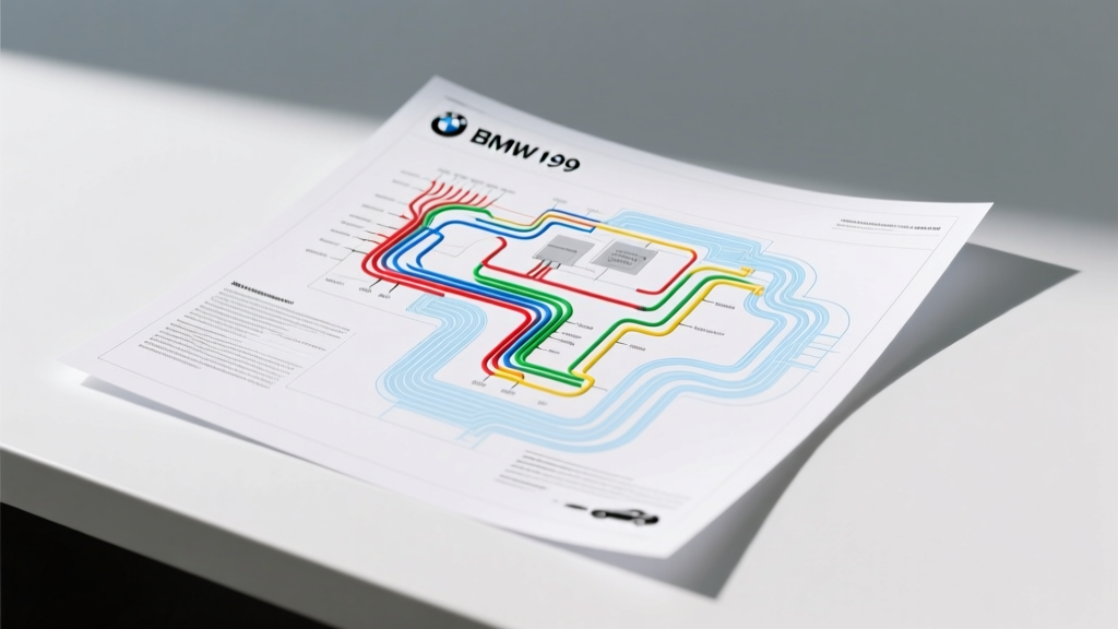
Navigating the BMW E90 Wiring Diagram PDF Architecture
The BMW E90 (2006-2011 3 Series) represents a massive paradigm shift in automotive electrical architecture, transitioning from traditional point-to-point wiring to highly integrated, module-driven CAN-bus networks. When diagnosing electrical gremlins in the E90, a standard multimeter is not enough; you must rely on a comprehensive BMW E90 wiring diagram PDF sourced from the BMW Wiring Diagram System (WDS) or Technical Information System (TIS). These PDFs do not look like traditional schematics. Instead, they utilize a matrix-based coordinate system, alphanumeric component identifiers (e.g., A11 for the DME, A40 for the Footwell Module), and specific connector designations (e.g., X60004, X1143).
Understanding how to read these PDF diagrams is the difference between a swift repair and a cascading electrical failure. According to the NewTIS BMW Technical Archive, BMW categorizes circuits by function, separating Powertrain CAN (PT-CAN) from Body CAN (K-CAN) and FlexRay networks. This step-by-step troubleshooting flow will guide you through interpreting these schematics and applying them to real-world E90 diagnostics.
Step-by-Step E90 Electrical Troubleshooting Flow
Follow this systematic decision tree when using your BMW E90 wiring diagram PDF to isolate faults. This methodology prevents unnecessary module replacement and focuses on harness integrity, voltage drops, and signal validation.
Step 1: Symptom Verification & Network Isolation
Before opening a single PDF page, connect an OBD2 scanner capable of BMW-specific module communication (such as INPA, ISTA+, or Foxwell). Read fault codes across all modules, not just the DME. If you see multiple 'Communication Lost' codes for modules on the same network (e.g., FRM, JBE, and KOMBI all missing on K-CAN), your issue is likely a network short or termination failure, not individual module death. Note the specific missing modules to cross-reference with the network topology page in your wiring diagram PDF.
Step 2: Schematic Cross-Referencing & Connector Location
Once the faulty circuit or network is identified, open the corresponding BMW E90 wiring diagram PDF. Locate the target component's alphanumeric code (e.g., A40 for the FRM). Follow the lines to the primary harness connector, designated by an 'X' followed by a 4-to-5 digit number (e.g., X1143). The PDF will provide a 'Connector View' page detailing the exact pinout, wire color, and cross-sectional area (mm²). Crucial Note: BMW wire colors are denoted by two letters or words (e.g., GN/WS for Green/White, OR/RT for Orange/Red).
Step 3: The Voltage Drop & Continuity Protocol
Never rely solely on a simple continuity beep test for E90 sensor or power circuits; a single strand of 0.5mm² (20 AWG) wire can carry a beep but fail under load. Perform a dynamic voltage drop test. For example, if testing the Crankshaft Position Sensor (CKP) 5V reference wire (Green/White), back-probe the connector while the ignition is ON. A healthy circuit will show less than a 0.1V drop between the DME pin and the sensor pin. If your BMW E90 wiring diagram PDF shows Terminal 30 (Battery Power) feeding the Junction Box Electronics (JBE) via a 2.5mm² (13 AWG) Red wire, a voltage drop greater than 0.2V under cranking load indicates internal harness corrosion or a failing crimp terminal.
Step 4: CAN-Bus Oscilloscope Validation
The E90 relies heavily on differential CAN-bus signaling. Using your wiring diagram PDF, identify the K-CAN High (Orange/Black) and K-CAN Low (Orange/Brown) wires. Connect an oscilloscope to these circuits. A healthy K-CAN network will show High resting at ~2.5V and Low resting at ~2.5V, swinging inversely during data transmission. If the PDF indicates a splice node (e.g., SP800), and your scope shows a flattened K-CAN Low signal, you have a short to ground downstream of that splice. Always check the termination resistors (located inside the DME and JBE); you should measure approximately 60 ohms across the CAN-High and CAN-Low pins with the battery disconnected.
Critical E90 Connector Pinout & Wire Color Reference
The table below highlights high-failure-point connectors frequently referenced in BMW E90 wiring diagram PDFs. Always verify against your specific model year's WDS PDF, as mid-cycle LCI (2009+) updates altered some pin assignments.
| Component / Module | Connector ID | Pin | Wire Color (BMW Code) | Wire Size (mm² / AWG) | Function / Terminal |
|---|---|---|---|---|---|
| DME (Engine Control) | X60004 | 19 | GN/WS (Green/White) | 0.5mm² (20 AWG) | CKP Sensor 5V Reference |
| DME (Engine Control) | X60004 | 18 | GR/GE (Gray/Yellow) | 0.5mm² (20 AWG) | CKP Sensor Signal |
| FRM (Footwell Module) | X1143 | 1 | OR/SW (Orange/Black) | 0.35mm² (22 AWG) | K-CAN High |
| FRM (Footwell Module) | X1143 | 2 | OR/BR (Orange/Brown) | 0.35mm² (22 AWG) | K-CAN Low |
| CAS (Car Access System) | X11 | 15 | RT/WS (Red/White) | 1.5mm² (15 AWG) | Terminal 30 (Constant 12V) |
| JBE (Junction Box) | X8000 | 12 | BR (Brown) | 2.5mm² (13 AWG) | Terminal 31 (Main Ground) |
Real-World E90 Failure Modes & Physical Inspection
A wiring diagram PDF only tells you how the system should work. As an automotive electrical expert, you must know where the E90 platform physically fails. Here are the most common real-world scenarios that require schematic-guided troubleshooting:
1. Junction Box Electronics (JBE) Corrosion
The E90's JBE is located behind the glovebox, directly beneath the windshield cowl drain. If the cowl drain clogs with debris, water backs up and drains directly onto the JBE and its massive X8000 and X8001 connectors. When diagnosing random interior electrical faults (windows, wipers, interior lights), consult the wiring diagram PDF to trace Terminal 30 and K-CAN lines into the JBE. Physically disconnect the X8000 connector and inspect for green/white copper oxide corrosion. If found, the harness must be cut back, and new SAE J2223 compliant crimp terminals must be installed using a proper ratcheting crimp tool and dual-wall heat shrink.
2. Footwell Module (FRM) EEPROM Corruption
The FRM controls exterior lighting, power windows, and interior lighting. A common E90 issue is 'FRM Bricked' following a weak battery crank. The starter motor pulls immense current, causing system voltage to drop below 9V. The FRM's EEPROM fails mid-write, corrupting the software. Before replacing the FRM, use your wiring diagram PDF to verify that the main power feeds (Terminal 30 and Terminal 15) at connector X1142 are delivering a clean 12.4V with zero AC ripple. If power is perfect but the module won't communicate on K-CAN, the module requires EEPROM reflashing or replacement and coding via INPA/NCS Expert.
3. PT-CAN Shorts at the DME Harness
The Powertrain CAN (PT-CAN) connects the DME, EGS (Transmission), and ABS/DSC modules. The harness routing near the E90 engine block is subjected to extreme heat and vibration. The Orange/Red (High) and Orange/Brown (Low) wires often chafe against the engine lifting bracket or intake manifold runners. If ISTA+ shows a PT-CAN bus short, use the PDF to locate the primary PT-CAN splice node. Perform a 'breakout' test: disconnect modules one by one while monitoring the CAN-High/Low resistance. If the short remains with all modules unplugged, the fault lies in the physical harness.
Professional Repair Standards & Best Practices
When your troubleshooting flow dictates a harness repair, never use twist-and-tape methods or standard solder on high-vibration sensor circuits. Solder creates a rigid joint that will work-harden and snap under engine vibration. According to Pelican Parts BMW Technical Guides and OEM repair standards, all E90 wiring repairs must utilize open-barrel copper crimps with marine-grade adhesive heat shrink. For high-current circuits (like the 40A alternator B+ cable or the 1.5mm² ignition feeds), ensure your crimping tool is calibrated for the specific metric wire gauge. Using an AWG-crimper on a 0.75mm² BMW wire will result in an under-crimped terminal, leading to increased resistance, localized heating, and eventual voltage drop.
Conclusion
Successfully diagnosing the BMW E90 requires moving beyond guesswork and embracing a methodical, schematic-driven approach. By leveraging a detailed BMW E90 wiring diagram PDF, understanding the matrix connector nomenclature, and applying rigorous voltage drop and oscilloscope testing protocols, you can accurately isolate faults within the PT-CAN, K-CAN, and hardwired sensor circuits. Always respect the metric wire sizing, adhere to SAE crimping standards, and address the platform's known environmental vulnerabilities, such as the cowl drain water ingress, to ensure a permanent repair.