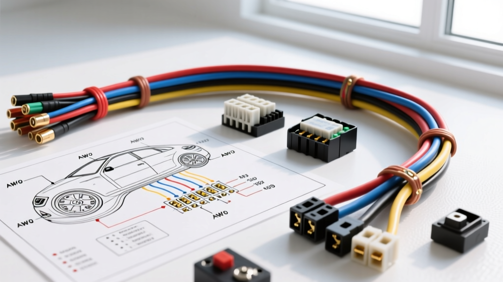
Introduction: The True Cost of Headlight Wiring Repairs
When upgrading or repairing automotive lighting, guessing wire routes and relying on hardware-store electrical tape leads to melted harnesses, blown fuses, and intermittent failures. A factory-accurate car headlight wiring diagram is your absolute blueprint for success. However, knowing the schematic is only half the battle; executing the repair requires specific automotive-grade tools and materials. Many DIYers and amateur mechanics underestimate the cost of proper terminal crimping and sealed connectors, resulting in premature corrosion in the engine bay.
This guide breaks down the exact cost and tool requirements to properly wire, upgrade, or troubleshoot headlight circuits using OEM diagrams. Whether you are integrating a relay harness for high-draw halogen bulbs or bypassing a CANbus system for LEDs, understanding the financial and technical requirements upfront will save you hundreds of dollars in misdiagnosed parts.
Decoding the Car Headlight Wiring Diagram: Core Architecture
Most modern and late-model classic vehicles use a relay-switched headlight circuit to protect the Body Control Module (BCM) or multifunction steering column switch from high current loads. When reading your vehicle's schematic, you will typically identify a standard ISO 7588-1 mini-relay architecture.
Standard Relay Pinout and Wire Sizing
- Pin 30 (Battery Feed): Requires 10 AWG wire. This circuit carries the full amperage load from the battery (fused at 20A or 30A) to the relay.
- Pin 87 (Normally Open Output): Requires 10 AWG or 12 AWG wire. This routes power directly to the headlight connector (e.g., H4, H7, or 9005).
- Pin 86 (Switch Trigger): Requires 14 AWG or 16 AWG wire. This carries the low-amperage signal from the BCM or headlight switch to energize the relay coil.
- Pin 85 (Coil Ground): Requires 14 AWG or 16 AWG wire. This completes the coil circuit to chassis ground.
According to SAE International (SAE J1128), automotive wire must be rated for high-temperature engine bay environments. Never use standard PVC building wire; you must use cross-linked polyethylene insulation like GXL, TXL, or SXL wire to prevent melting near the radiator and exhaust manifolds.
Tool Requirements: Essential vs. Optional
Automotive electrical work requires specific crimping dies for open-barrel terminals (like Delphi Weather-Pack or Metri-Pack). Using a generic $15 hardware store crimper will crush the wire strands, creating a high-resistance joint that will eventually melt the connector.
| Tool / Equipment | Specific Application | Estimated Cost | Necessity Level |
|---|---|---|---|
| Open-Barrel Terminal Crimper | Crimping Delphi/Aptiv Weather-Pack and Metri-Pack 280 terminals | $45 - $90 | Mandatory |
| Wire Stripper (AWG 10-18) | Stripping TXL/GXL thin-wall automotive wire without nicking copper | $20 - $35 | Mandatory |
| Digital Multimeter (DMM) | Voltage drop testing and continuity checks on ground circuits | $40 - $120 | Mandatory |
| Terminal Release Tool Set | Extracting pinned terminals from OEM headlight pigtails | $15 - $25 | Highly Recommended |
| Heat Gun with Reflector Nozzle | Shrinking adhesive-lined heat shrink for environmental sealing | $35 - $60 | Optional (Lighter works) |
| Tone Generator / Wire Tracer | Locating specific trigger wires inside dense BCM harnesses | $30 - $50 | Optional |
For professional-grade crimping, tools like the Delphi (Aptiv) specific crimpers or high-end aftermarket equivalents ensure the terminal bellmouth is formed correctly, which is critical for pull-out force retention. You can find detailed assembly specifications for these sealed connectors via Aptiv Weather-Pack distributor guides.
Material Cost Analysis: Custom Harness vs. Pre-Made Kits
When your car headlight wiring diagram reveals degraded factory wires or an inadequate gauge for an upgraded bulb, you face a decision: build a custom harness or buy a pre-made relay kit.
Option A: The Pre-Made H4/H7 Relay Harness
Aftermarket relay harnesses (often sold for $25-$40) are plug-and-play. They plug directly into the OEM headlight bulb and use the factory circuit merely as a trigger. The downside: These kits almost universally use cheap PVC wire, unsealed spade connectors on the relay, and lack proper fusing near the battery. They are a temporary fix and highly susceptible to under-hood moisture intrusion.
Option B: The Custom OEM-Spec Harness
Building your own harness based strictly on the factory schematic costs slightly more upfront but yields a lifetime repair.
- 10 AWG TXL Wire (25 ft): $18.00
- Bosch-Style ISO Mini Relays (Sealed): $8.00 each
- Delphi Weather-Pack 2-Way Connectors (Pigtails): $6.50 per pair
- Inline Maxi-Fuse Holder & 20A Fuse: $7.00
- Adhesive-Lined Heat Shrink & Loom: $12.00
Total Custom Cost: ~$51.50. While $15 more than a cheap Amazon harness, the custom build utilizes sealed connections, proper strain relief, and high-temp wire, eliminating the risk of an engine bay electrical fire.
Troubleshooting Voltage Drop Using the Schematic
A common issue identified when analyzing a car headlight wiring diagram is dim lighting, even with brand-new bulbs. This is rarely a bulb issue; it is a voltage drop caused by factory ground degradation. According to Haynes automotive electrical testing protocols, you should never test a ground by simply checking for continuity to the battery negative terminal. Continuity checks do not reveal high resistance under load.
The Voltage Drop Test Procedure
- Turn the headlights ON (engine running to simulate alternator output).
- Set your DMM to DC Volts.
- Place the red probe on the battery positive terminal and the black probe on the headlight connector's power pin. A reading above 0.5V indicates excessive resistance in the positive feed (corroded relay contacts or undersized wire).
- Place the red probe on the headlight connector's ground pin and the black probe on the battery negative terminal. A reading above 0.2V indicates a failed chassis ground.
The wiring diagram will direct you to the specific ground node (e.g., G104 or G200, typically located on the inner fender well or strut tower). The fix requires removing the ground bolt, sanding the paint and corrosion down to bare metal, applying dielectric grease, and torquing the bolt to the manufacturer's specification (usually 8-10 Nm for M6 ground bolts).
Advanced Integration: CANbus and PWM Bypass Modules
If you are using the wiring diagram to upgrade from halogen to LED or HID, modern vehicles (2010+) present a new challenge. Many BCMs use Pulse Width Modulation (PWM) to run daytime running lights (DRLs) at a reduced voltage, and they monitor circuit current to detect 'out' bulbs.
Because LEDs draw a fraction of the amperage of a 55W halogen bulb, the BCM will trigger a 'bulb out' warning on the dash and may cut power entirely. Your wiring diagram will show the CANbus lines interacting with the lighting control module. To fix this cost-effectively without flashing the ECU:
- PWM Bypass Relay ($15): Wired between the factory trigger and your new LED driver, this relay uses a capacitor to smooth out the PWM signal into a solid 12V+ trigger.
- Load Resistors ($10/pair): Wired in parallel on the positive and negative legs of the headlight pigtail to simulate the 55W draw. Warning: Resistors generate extreme heat and must be mounted to a metal chassis surface, never zip-tied to plastic or wire loom.
Conclusion
Successfully navigating a car headlight wiring diagram requires more than just reading lines and symbols; it requires an investment in the correct open-barrel crimping tools and SAE-rated TXL/GXL materials. By understanding the true cost of OEM-spec components versus cheap aftermarket shortcuts, you can execute a lighting repair or upgrade that is safe, reliable, and immune to engine bay environments.