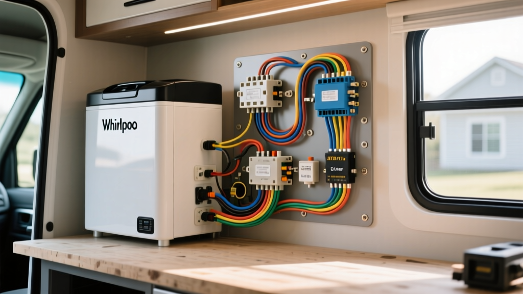
Integrating Residential Appliances into Vehicle Electrical Systems
The modern overlanding and camper van movement has blurred the lines between automotive electrical engineering and residential comfort. Upfitters frequently install household appliances into 12V or 24V DC chassis architectures, requiring a deep understanding of both automotive standards and appliance load characteristics. When builders search for a standard wiring diagram for whirlpool ice maker units, they are typically presented with internal factory schematics detailing the thermostat, water inlet valve, and compressor relays. However, in a vehicle environment, the true challenge lies in the external integration: safely bridging a high-surge inductive load to a lithium battery bank via an inverter without triggering a Battery Management System (BMS) fault or causing excessive voltage drop.
This guide approaches the installation from a Beginner-Friendly Fundamentals perspective, breaking down the exact wire gauges, overcurrent protection, and inverter topologies required to run a residential Whirlpool ice maker off a vehicle's auxiliary electrical system.
Decoding the Integration Topology
Unlike a hardwired 12V automotive accessory (such as a light bar or winch), a Whirlpool ice maker requires 120V AC power. Therefore, the 'wiring diagram' for a vehicle installation is actually a multi-stage topology consisting of three distinct circuits:
- The High-Current DC Circuit: Battery bank to the inverter DC terminals.
- The AC Distribution Circuit: Inverter AC output to the sub-panel and GFCI receptacle.
- The Water Supply Circuit: Adapting the 120V AC water solenoid to a 12V DC off-grid water pump system (optional but highly recommended for boondocking).
Load Analysis: Compressors and Inductive Surges
Before sizing your wiring, you must understand the electrical footprint of the ice maker. Whirlpool residential ice makers utilize a sealed compressor system to freeze the water and a solenoid valve to fill the mold. Compressors are inductive loads. While the running wattage may only be 120W to 180W (roughly 1.0 to 1.5 Amps at 120V AC), the startup surge—known as Locked Rotor Amps (LRA)—can spike to 800W or more for a fraction of a second.
If you use a Modified Sine Wave (MSW) inverter, the compressor will run hot, inefficiently, and may eventually fail due to harmonic distortion. You must use a Pure Sine Wave (PSW) inverter rated for at least 2000W continuous to handle the micro-surge without tripping the inverter's internal over-current protection.
DC Architecture: Battery Bank to Inverter
The most common point of failure in camper van builds is undersized DC wiring between the battery bank and the inverter. According to the Victron Energy Wiring Unlimited Guide, inverter cables must be sized not just for continuous amperage, but to minimize voltage drop, which can cause the inverter to prematurely shut down during the ice maker's compressor startup surge.
Calculating the DC Wire Gauge
A 2000W inverter pulling from a 12V nominal lithium battery bank (which actually sits around 13.2V) will draw approximately 151 Amps continuously at full load, and potentially over 200 Amps during a surge. To keep voltage drop under 1% for a standard 5-foot one-way cable run, you must use heavy-gauge automotive battery cable.
- Wire Gauge: 2/0 AWG (or 4/0 AWG for runs longer than 5 feet) stranded copper battery cable.
- Insulation: SAE J1127 compliant, fine-stranded for flexibility in vehicle chassis routing.
- Terminations: 3/8-inch tinned copper ring terminals, crimped with a hex-die hydraulic crimper. Torque inverter lugs to manufacturer specifications (typically 5 to 7 Nm).
- Overcurrent Protection: A 250-Amp Class T fuse installed on the positive cable, within 18 inches of the battery bank positive terminal. Class T fuses are essential because they possess a high Ampere Interrupting Capacity (AIC) of 20,000 Amps, safely protecting against catastrophic lithium short-circuit events.
AC Architecture: Inverter to Appliance
Once the DC power is inverted to 120V AC, it must be routed safely to the ice maker. Automotive electrical standards dictate that AC and DC wiring must be separated by at least 1.5 inches to prevent electromagnetic interference (EMI) and reduce the risk of a short circuit crossing high-voltage AC into low-voltage DC control systems.
AC Wiring Specifications
- Wire Gauge: 10 AWG or 12 AWG stranded THHN/THWN copper wire.
- Color Code: Black (Hot), White (Neutral), Green (Ground).
- Protection: Route the Black (Hot) wire through a 15-Amp or 20-Amp AC DIN-rail breaker in your van's sub-panel.
- Receptacle: Terminate at a 15-Amp GFCI (Ground Fault Circuit Interrupter) NEMA 5-15R outlet. The GFCI is a non-negotiable safety requirement in any vehicle where water and electricity coexist, aligning with NFPA 1192 Standard on Recreational Vehicles.
Advanced Mod: Swapping the AC Water Valve for 12V DC
Here is where automotive wiring expertise truly elevates a camper van build. The OEM Whirlpool ice maker uses a 120V AC water inlet valve (often part number WPW10179146) to draw water from the household supply. In an off-grid vehicle, you are likely pulling water from a 12V DC pressurized accumulator tank or an on-demand 12V diaphragm pump.
Running a 120V AC solenoid valve off an inverter just to open a water line for 4 seconds is highly inefficient. Advanced upfitters swap the OEM AC solenoid for a 12V DC Reverse Osmosis (RO) Solenoid Valve (1/4-inch quick-connect).
The 12V Solenoid Bypass Wiring Diagram
- Remove the OEM 120V AC water valve from the Whirlpool harness.
- Install a 12V DC inline solenoid valve on the PEX water line feeding the ice maker.
- Wire the 12V solenoid to a standard 12V automotive Bosch relay (P/N 0 332 014 150).
- Use an AC-to-DC optocoupler relay to sense when the ice maker's internal control board sends 120V AC to the original valve circuit. The optocoupler safely triggers the 12V DC automotive relay without bridging the AC and DC systems.
- Fuse the 12V solenoid branch circuit with a 2-Amp ATC blade fuse.
This modification eliminates the need to keep the 2000W inverter powered on just to harvest ice, allowing the ice maker's low-wattage thermostat to run directly off a dedicated 12V DC-to-DC step-down converter while the compressor only kicks on when the inverter is active.
Reference Chart: Inverter Sizing and Cable Specifications
| Inverter Size (Continuous) | Max DC Draw (12V System) | Recommended DC Cable (Up to 5ft) | DC Fuse Rating (Class T) | AC Output Wire |
|---|---|---|---|---|
| 1000W | ~85 Amps | 2 AWG | 125 Amp | 12 AWG THHN |
| 2000W | ~170 Amps | 2/0 AWG | 250 Amp | 10 AWG THHN |
| 3000W | ~255 Amps | 4/0 AWG | 350 Amp | 10 AWG THHN |
Troubleshooting Common Inverter and Ice Maker Faults
When integrating residential appliances into automotive DC systems, issues rarely stem from the appliance itself. Use this diagnostic tree to isolate faults:
- Symptom: Ice maker clicks, but compressor fails to start; inverter alarms.
Cause: Voltage drop on the DC side is causing the inverter's low-voltage cutoff to trigger during the LRA surge.
Fix: Upgrade DC cabling from 2 AWG to 2/0 AWG and check for loose crimps on the busbar terminals. - Symptom: Ice maker control board throws an error code or water valve hums without opening.
Cause: Modified Sine Wave inverter causing harmonic distortion, or neutral-ground bond issues.
Fix: Verify inverter is Pure Sine Wave. Ensure the inverter's internal transfer switch or AC sub-panel has a proper Neutral-to-Ground bond, which is required for many residential appliance GFCI and control boards to function correctly. - Symptom: BMS shuts down entirely when ice maker cycles.
Cause: The continuous draw combined with other 12V loads exceeds the BMS discharge limit (e.g., a 100A BMS trying to supply a 150A surge).
Fix: Add a secondary battery in parallel to increase discharge capacity, or upgrade to a BMS rated for 200A+ continuous discharge.
By treating the wiring diagram for whirlpool ice maker integration as a holistic automotive upfit project rather than a simple plug-and-play appliance install, you ensure reliable, off-grid ice production that adheres to rigorous mobile electrical safety standards. For further reading on marine and mobile AC/DC integration standards, refer to the ABYC E-11 AC/DC Electrical Systems Standard, which serves as the gold standard for high-end vehicle conversions.