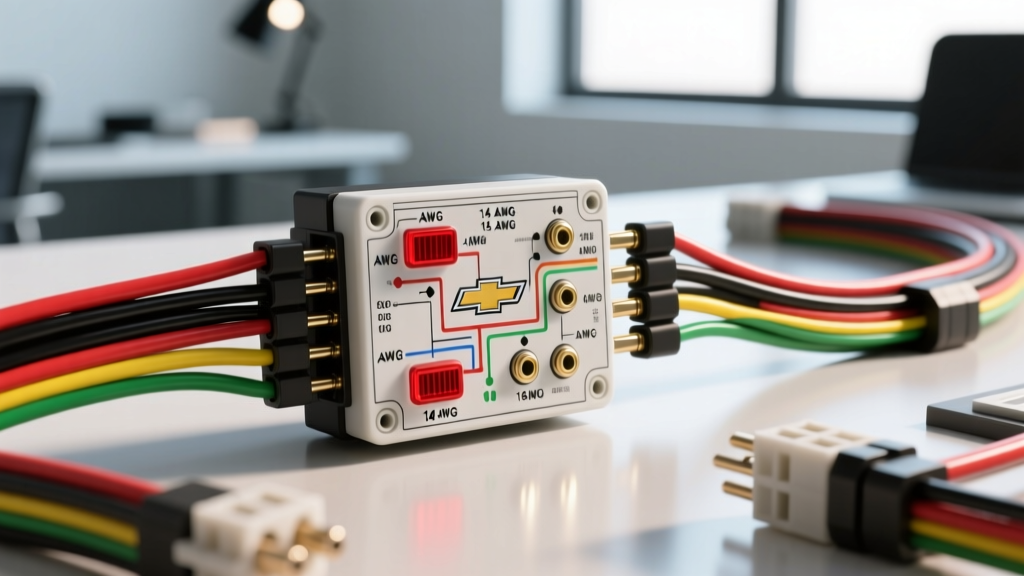
Understanding the Chevy Rear Junction Block
If you own a GM truck or SUV from the GMT800 era (1999–2006 Chevy Silverado, GMC Sierra, Tahoe, or Suburban), you have likely encountered the infamous rear lighting failure. The culprit is almost always the rear junction block. For beginners diving into automotive electrical repair, understanding the Chevy tail light junction block wiring diagram is the first step toward diagnosing and permanently fixing flickering, dim, or completely dead tail lights, brake lights, and turn signals.
The rear junction block acts as a central distribution hub. Instead of running individual, continuous wires from the front Body Control Module (BCM) or under-hood fuse block all the way to each tail light and the trailer hitch connector, GM engineers used this block to split the main rear harness into the left-side, right-side, and trailer plug pigtails. While this modular design made factory assembly and tow-package integration easier, it created a massive vulnerability: the block is located on the driver-side rear frame rail, directly in the path of road spray, mud, and salt.
Decoding the Chevy Tail Light Junction Block Wiring Diagram
Before grabbing a multimeter or a pair of wire crimpers, you need to know what goes in and what comes out. The standard GM rear junction block utilizes a multi-pin connector that interfaces with the main chassis harness. Below is the fundamental wiring schematic breakdown for the standard 6-way rear lighting connector.
| Pin | Wire Color | Function | AWG Size | Terminal Type |
|---|---|---|---|---|
| A | Dark Green | Right Turn / Stop Lamp | 18 AWG | Metri-Pack 280 |
| B | Yellow | Left Turn / Stop Lamp | 18 AWG | Metri-Pack 280 |
| C | Brown | Tail / Park / Marker Lamps | 18 AWG | Metri-Pack 280 |
| D | Black | Primary Chassis Ground | 14 AWG | Metri-Pack 280 |
| E | Light Blue | Auxiliary / Backup Lamps | 18 AWG | Metri-Pack 280 |
| F | White | Secondary Ground / Trailer | 14 AWG | Metri-Pack 280 |
Why Wire Gauge and Terminal Type Matter
Notice the difference in American Wire Gauge (AWG) sizes in the diagram above. The lighting circuits (turn, stop, park) use 18 AWG wire, which is perfectly sufficient for the low amperage draw of standard 1157 and 3157 incandescent bulbs. However, the ground circuits (Pins D and F) step up to a thicker 14 AWG wire. According to the SAE J1128 Low Tension Cable Standard, a smaller gauge number means a thicker wire capable of carrying more current with less resistance. Because the ground circuit must handle the combined return current of all rear lighting and trailer accessories, a thicker 14 AWG wire prevents voltage drops and overheating.
Furthermore, GM uses Delphi (now Aptiv) Metri-Pack 280 series terminals inside this block. These are robust, flat-blade connectors designed for high-vibration environments. When repairing this harness, using standard butt connectors is a rookie mistake; you must use adhesive-lined heat shrink and, ideally, replacement Metri-Pack pigtail connectors to maintain factory-level weather resistance.
Common Failure Symptoms and Diagnostic Trees
Because the junction block is essentially an unsealed plastic box exposed to the elements, water enters via capillary action. Over time, the copper terminals oxidize, creating a high-resistance bottleneck. Here is how to diagnose the issue based on your specific symptoms:
- Symptom: Tail lights are out, but brake lights and turn signals work.
Cause: Corrosion isolated to Pin C (Brown wire) or a blown TRL PARK fuse in the under-hood block. - Symptom: Right turn signal hyper-flashes, but bulb is new.
Cause: High resistance on Pin A (Dark Green) inside the junction block, causing the BCM to read an open circuit. - Symptom: All rear lights are dim; brake light illuminates when turning on headlights.
Cause: Complete failure of Pin D (Black Ground). The system is back-feeding through the filaments to find a ground elsewhere. Check Ground G401 and G402 located on the rear frame crossmembers.
For accurate diagnosis, the Haynes Electrical Testing Guide highly recommends performing a voltage drop test rather than simply checking for continuity. A circuit can show 12 volts with a multimeter but fail to carry the amperage needed to light a bulb due to severe internal corrosion.
Step-by-Step Junction Block Bypass and Repair
When the internal terminals are green with copper sulfate corrosion, cleaning them is only a temporary band-aid. The most reliable, permanent fix favored by GM technicians is to bypass the junction block entirely or splice in a new sealed pigtail. Here is the beginner-friendly, step-by-step repair procedure:
- Disconnect the Battery: Always disconnect the negative battery terminal to prevent shorting the 14 AWG ground circuits against the chassis while cutting.
- Locate and Extract: Find the black junction block on the driver-side rear frame rail, just forward of the spare tire. Push the plastic retaining tab upward to slide the block off the frame stud.
- Cut the Harness: Cut the wires approximately 3 inches above and below the junction block. This gives you enough slack to strip and crimp. Pro Tip: Cut one wire at a time to keep your color-coding organized, or tape and label them first.
- Strip and Crimp: Strip 3/8 inch of insulation from each wire. Match the colors exactly according to the wiring diagram table above. Use a ratcheting wire crimper to secure adhesive-lined heat shrink butt connectors.
- Seal the Connections: Apply heat with a heat gun until the adhesive oozes out of the ends of the shrink tubing. This creates a waterproof seal that prevents future capillary corrosion.
- Secure the Harness: Zip-tie the newly spliced harness securely to the frame rail, ensuring it is routed away from the exhaust system and moving suspension components.
- Apply Dielectric Grease: If you are plugging into a trailer connector pigtail, apply a generous amount of silicone dielectric grease to the terminals to displace moisture.
Addressing the Rear Ground Points (G401 & G402)
Even with a brand-new junction block or a perfect bypass splice, your tail lights will malfunction if the final destination grounds are compromised. GM designates the left rear ground as G401 and the right rear ground as G402. These are typically 5/16-inch bolts securing a cluster of ring terminals directly to the bare metal of the rear frame or bed support.
To service these, remove the bolt, clean the frame contact patch with a wire brush or sandpaper down to bare, shiny metal, and clean the ring terminals. Reattach the grounds, torque the bolt to factory specifications (typically 10-15 lb-ft for small frame grounds), and coat the entire assembly in battery terminal protector spray or grease to halt future rust.
Summary and Further Resources
Troubleshooting the Chevy tail light junction block wiring diagram does not require an engineering degree, but it does demand respect for OEM wire gauges, proper sealing techniques, and systematic testing. By understanding the color codes, recognizing the failure points of the GMT800 rear harness, and executing a proper, weather-sealed splice, you can restore your truck's lighting system to better-than-factory condition. For more advanced BCM diagnostics and factory service bulletins regarding GM lighting modules, refer to archived GM TechLink publications, which provide invaluable dealer-level insights into recurring electrical gremlins.