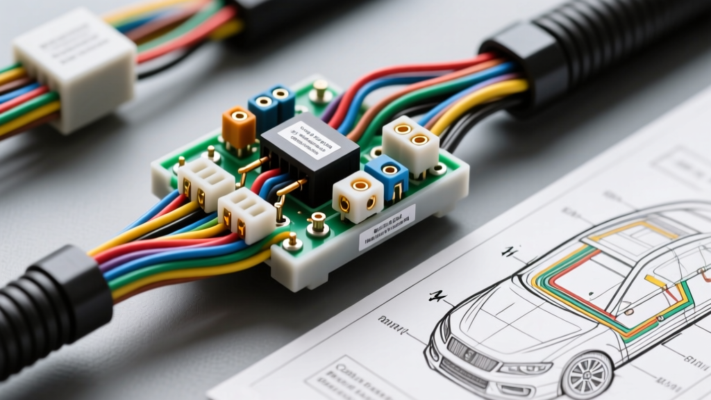
The Hidden Costs of Automotive Electrical Drafting
When executing complex automotive builds—such as LS-engine swaps, EV conversions, or full restomod rewiring—the physical harness is only as reliable as the schematic it was built from. Misinterpreting a schematic or using inadequate drafting tools doesn't just waste time; it results in catastrophic financial losses. A misunderstood ground symbol can fry a $450 OEM Engine Control Module (ECM), while poor wire gauge selection based on a misread diagram can cause a harness meltdown. Understanding the common electrical symbols used in sketching wiring plan and diagram layouts is the first step in mitigating these risks. However, mastering these symbols requires the right ecosystem of software, physical tracing tools, and crimping hardware. This guide breaks down the true cost of automotive wiring documentation and the tools required to translate paper sketches into loomed, engine-ready harnesses.
Tool Requirements & Cost Breakdown: Digital vs. Analog
Creating a vehicle-specific wiring diagram requires a blend of digital design software and physical verification tools. The initial capital expenditure for these tools varies wildly depending on whether you are a DIY builder sketching a single harness or a professional shop designing bespoke PDM (Power Distribution Module) systems.
Software & Digital Schematic Tools
- AutoCAD Electrical / SolidWorks Electrical: The industry standard for professional harness manufacturers. These platforms feature built-in automotive wire libraries (TXL, GXL, SXL), automated BOM (Bill of Materials) generation, and SAE-compliant symbol libraries. Cost: $5,000 - $8,000+ annually.
- Microsoft Visio (Professional): A common middle-ground for custom hot rod shops. While it lacks automated wire routing, it allows for clean, scalable vector sketches of ECU pinouts and relay logic. Cost: ~$250 (one-time) or $15/month.
- QElectroTech / KiCad (Open Source): Highly capable free alternatives. QElectroTech is particularly well-suited for automotive relay logic and fuse block sketching. Cost: $0 (Requires manual symbol library creation).
Physical Prototyping & Tracing Hardware
Sketching the diagram is only half the battle; verifying the OEM harness against your sketch requires precision diagnostic tools.
- Fluke 87V Automotive Multimeter: Essential for tracing PWM signals, verifying CAN-bus termination resistance (60 ohms), and mapping ECU pinouts. Cost: ~$450.
- Brother PT-51BM Wire Label Printer: Industrial-grade wire labeling. Properly labeling both ends of an 18 AWG sensor wire before crimping is mandatory for complex harnesses. Cost: ~$60 + $40 for heat-shrink tubing cassettes.
- Daniels Manufacturing AFM8 Crimp Tool: The gold standard for crimping Delphi/Packard Metri-Pack and Weather-Pack terminals. Generic ratcheting crimpers ($45) often yield inconsistent pull-test results on 20 AWG ECU wires. Cost: ~$350.
Decoding Common Electrical Symbols Used in Sketching Wiring Plan and Diagram
The SAE J1292 standard governs automotive electrical symbols, ensuring that a schematic drawn in Detroit can be read by a technician in Tokyo. When analyzing the common electrical symbols used in sketching wiring plan and diagram documents, you must differentiate between power distribution symbols and low-voltage signal logic.
Grounding Symbols: Chassis vs. Signal
One of the most expensive mistakes in custom wiring is conflating chassis grounds with signal grounds. In standard automotive sketching:
- Chassis Ground (Symbol: Three descending horizontal lines): Indicates a physical connection to the vehicle's steel/aluminum frame. Used for high-current returns like starter motors, alternator cases, and lighting circuits. Typically requires 10 AWG to 4 AWG ring terminals.
- Signal/Clean Ground (Symbol: Three descending lines enclosed in a circle or triangle): Indicates a dedicated ground wire returning directly to the ECU or sensor ground plane. Used for Mass Air Flow (MAF) sensors and O2 sensors. Connecting a signal ground to a noisy chassis ground will introduce electromagnetic interference (EMI), causing erratic fuel trims.
Splices and Connectors
OEM wiring diagrams use specific alphanumeric codes to denote splices and connectors. A symbol marked S100 denotes a physical copper crimp splice (usually wrapped in adhesive-lined heat shrink) hidden inside the harness loom. A symbol marked C205 denotes a mateable connector (e.g., a 4-pin Metri-Pack 280). Understanding these symbols dictates your tooling: splices require adhesive heat shrink and a heat gun, while connectors require specific terminal insertion tools and cavity plugs.
Symbol-to-Specification Translation Matrix
Translating 2D symbols into physical 3D harnesses requires strict adherence to SAE J1128 wire specifications. The table below maps common schematic symbols to their physical automotive requirements and associated material costs.
| Schematic Symbol / Node | Automotive Application | Wire Spec (SAE J1128) | Terminal / Connector Type | Est. Material Cost (Per Node) |
|---|---|---|---|---|
| Ignition Switch (Start/Run) | ECM Main Power Relay Coil | 16 AWG TXL (Pink) | Delphi Metri-Pack 280 Female | $1.25 |
| Shielded Signal Wire | Crankshaft Position Sensor (CKP) | 20 AWG Shielded Twisted Pair | Delphi Metri-Pack 150 Series | $4.50 |
| High-Current Splice (S-Node) | Alternator B+ to Starter Junction | 4 AWG SXL (Red) | Adhesive-Lined Butt Splice / Copper Tube | $6.00 |
| CAN-Bus Terminator | OBD-II Port Pins 6 & 14 | 18 AWG Shielded (Tan/Tan-White) | 120-Ohm Resistor (Integrated) | $3.50 |
Case Study: Budgeting a Custom 5.3L LS-Swap Harness
To illustrate the cost and tool requirements in a real-world scenario, let us examine the process of sketching and building a custom engine harness for a 5.3L LM7 Vortec engine swap. The factory harness is often too bulky or damaged, necessitating a custom build from the ECU to the engine sensors.
Delphi 80-Way ECU Pinout & Wire Specs
The GM LS1/LS2 PCM utilizes a Delphi/Packard 80-way connector (Part #15326843). When sketching this plan, your diagram must account for specific wire gauges based on the symbol's current draw:
- Pin 1 & Pin 2 (Ignition 12V): Represented by standard battery/ignition symbols. Requires 14 AWG TXL (Pink) to handle the amperage draw of the internal PCM drivers without voltage drop. Cost: ~$0.15/ft.
- Pin 21 (Class 2 Serial Data): Represented by a communication bus symbol. Requires 18 AWG (Tan/White). This wire routes to the OBD-II port and must be kept away from high-voltage ignition coils to prevent data corruption. Cost: ~$0.10/ft.
- Pins 73-80 (Power Grounds): Represented by heavy chassis ground symbols. Requires 12 AWG TXL (Black). These must terminate at a clean, bare-metal point on the engine block, requiring heavy-duty ring terminals and a 1/2-ton hydraulic crimp tool. Cost: ~$0.25/ft.
Total Tooling & Material Budget for LS Harness
For a one-off custom harness build, the financial breakdown looks like this:
- Drafting Software (Visio/QElectroTech): $0 - $250
- Delphi 80-Way ECU Pigtail & Terminals: $185
- TXL Wire (10 colors, 50ft spools): $320
- Ratcheting Crimpers & Pin Insertion Tools: $150
- TCA (Teflon Cloth Automotive) Harness Tape & Loom: $85
- Total Estimated Cost: $740 - $990
By accurately interpreting the common electrical symbols used in sketching wiring plan and diagram documents, builders avoid the $500+ cost of replacing blown ECM drivers caused by wiring a 14 AWG power circuit into a 20 AWG signal pin.