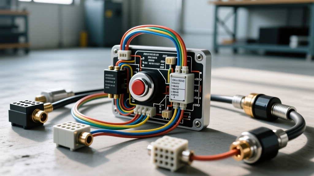
Architecting a High-Amperage Push Button Starter Circuit
When bypassing a degraded factory ignition cylinder for a dedicated race car, custom street rod, or heavy-duty agricultural build, relying on a standard push button starter switch wiring diagram found on generic forums often leads to melted terminals and catastrophic voltage drop. The starter motor is the single highest current-drawing component on any vehicle. During initial cranking, Locked Rotor Amperage (LRA) can spike between 400A and 800A before settling into a running draw of 150A to 250A. To handle this inductive load safely, your control circuit must be isolated from the high-current power circuit using heavy-duty relays and properly sized cabling.
This advanced technical deep dive outlines the exact engineering principles, wire gauge requirements, and terminal specifications required to build a bulletproof push-button start system. We will cover both GM-style (4-post) and Ford-style (3-post) starter solenoid configurations, ensuring your custom build cranks reliably under all thermal conditions.
Core Circuit Architecture: Isolating Control and Power
A common failure mode in amateur custom wiring is routing the starter solenoid's 'S' (Start) terminal current directly through a dashboard-mounted push button. The 'S' terminal typically houses a pull-in coil that draws between 15A and 30A momentarily. Most standard automotive momentary push buttons are rated for only 10A to 15A. Pushing 25A through a 15A switch causes rapid thermal degradation, carbon tracking across the contacts, and eventual welding of the switch internals, leaving the starter engaged after the engine fires.
The Bosch-Style Relay Isolation Method
To prevent switch failure, the industry standard is to use the push button exclusively as a low-current trigger for a high-amperage automotive relay. This reduces the load on the dashboard switch to less than 0.5A, virtually eliminating thermal failure.
- Control Circuit (Low Current): 14 AWG TXL wire, routed through a 5A fuse to the push button, then to the relay coil (Pins 85/86).
- Power Circuit (High Current): 10 AWG wire from the battery junction block to the relay switched contact (Pin 30), and from the relay output (Pin 87) to the starter solenoid 'S' terminal.
Solenoid Coil Physics: Pull-In vs. Hold-In
Inside the starter solenoid, there are actually two distinct electromagnetic coils: the pull-in coil and the hold-in coil. When the push button triggers the relay and sends 12V to the 'S' terminal, both coils are energized in parallel, creating a massive magnetic field to physically pull the heavy copper contact disc against the 'B' and 'M' terminals. This initial pull requires high amperage (up to 30A). Once the disc makes contact, the pull-in coil is shorted out by the main circuit current, and only the hold-in coil remains active, which requires less than 5A to keep the solenoid engaged. Understanding this dual-coil physics explains why undersized control wires often result in a rapid 'clicking' sound; the voltage drop across the thin wire starves the pull-in coil of the necessary amperage to complete the mechanical throw, causing the circuit to rapidly cycle on and off.
Step-by-Step Push Button Starter Switch Wiring Diagram
1. The High-Current Battery Path
The main power feed must originate directly from the battery positive terminal or the main distribution stud, never from a daisy-chained accessory block. According to SAE J1128 standards for low-tension primary cable, voltage drop in the cranking circuit must not exceed 0.50V total. For a standard V8 engine requiring 250A cranking current, a minimum of 2 AWG copper stranded wire is required for runs up to 10 feet. For runs exceeding 10 feet, or for high-compression diesel applications, upgrade to 1/0 AWG (0 AWG) battery cable.
2. GM-Style 4-Post Solenoid Configuration
GM starter solenoids (common on LS and Gen III+ V8s) feature four terminals: 'B' (Battery), 'M' (Motor), 'S' (Start), and 'R' (Resistor/Ballast Bypass).
- Terminal B (3/8-16 stud): Connects to Battery (+) via 2 AWG red cable.
- Terminal M (3/8-16 stud): Connects to the starter motor internal lug via a short 2 AWG braided strap.
- Terminal S (Spade): Receives 12V+ from the relay Pin 87 during cranking. Wire color: Yellow (10 AWG).
- Terminal R (Spade): Historically used to bypass the ballast resistor on points-style ignitions, providing full 12V to the coil during cranking. On modern EFI/LS engines, this terminal is typically left disconnected or capped to prevent back-feeding the ECU ignition circuits.
3. Ford-Style 3-Post Solenoid Configuration
Ford utilizes a remote-mounted fender solenoid (e.g., Cole Hersee 24059 or Motorcraft SW-3). This solenoid has two large 3/8-16 studs and one small 'S' spade terminal. The 'S' terminal receives the push-button relay trigger. The large studs act as the main high-current contactor, bridging the battery cable to the starter motor cable when energized.
Wire Gauge and Amperage Specification Chart
Selecting the correct AWG is critical. The chart below dictates minimum wire sizes based on SAE J1128 guidelines for 12V nominal systems, assuming a maximum allowable voltage drop of 3% (0.36V) for control circuits and 0.5V for high-current cranking circuits.
| Circuit Function | Max Continuous Amps | Peak Inrush (LRA) | Recommended AWG (Under 10ft) | Recommended AWG (Over 10ft) |
|---|---|---|---|---|
| Battery to Starter Solenoid (B) | 250A | 600A+ | 2 AWG | 1/0 AWG |
| Solenoid to Starter Motor (M) | 250A | 600A+ | 2 AWG | 2 AWG |
| Relay Pin 30 to 87 (S-Terminal Feed) | 30A | 45A | 10 AWG | 8 AWG |
| Push Button to Relay Coil (85/86) | 2A | N/A | 16 AWG | 14 AWG |
| ECU Ignition/Run Feed | 15A | N/A | 14 AWG | 12 AWG |
Connector Types and Crimping Standards
Hand-crimping high-amperage terminals with standard pliers is a primary cause of electrical fires in custom vehicles. For 2 AWG and 1/0 AWG battery cables, you must use closed-barrel copper ring terminals (e.g., Molex or TE Connectivity) crimped with a hydraulic or heavy ratcheting hex-crimp tool compliant with UL 486A-486B standards. The crimp must achieve a gas-tight seal to prevent oxidation and galvanic corrosion.
For the control circuit spade connectors mating to the 'S' terminal, use fully insulated, heat-shrink nylon female quick-disconnects. Apply dielectric grease (such as NO-OX-ID A-Special) to all bare copper and terminal mating surfaces before final torque. Torque the 3/8-16 solenoid nuts to exactly 85-110 in-lbs. Over-torquing will strip the soft copper threads inside the solenoid housing; under-torquing will result in micro-arcing and localized melting.
Advanced Troubleshooting: Voltage Drop Testing
If your custom push-button setup yields a slow crank or clicks without engaging the starter, do not immediately replace the starter. Perform a dynamic voltage drop test using a digital multimeter (DMM) while an assistant actuates the push button.
Decision Tree for Cranking Failures
- Test 1: Battery Health. Measure across the battery posts during cranking. If voltage drops below 9.6V, the battery is sulfated or undersized. Load test required.
- Test 2: Positive Cable Drop. Place DMM positive lead on battery (+) post and negative lead on solenoid 'B' terminal. Crank engine. A reading above 0.20V indicates high resistance in the 2 AWG cable or a corroded battery terminal.
- Test 3: Solenoid Internal Contact Drop. Place DMM leads across 'B' and 'M' terminals while cranking. A reading above 0.30V indicates pitted or carbon-fouled internal copper contacts inside the solenoid. Replace the solenoid.
- Test 4: Control Circuit Drop. Back-probe the 'S' terminal spade connector while cranking. If voltage at the 'S' terminal is below 10.5V (with battery at 12.6V), your relay contacts (Pin 30 to 87) or the 10 AWG feed wire are undersized or degraded.
By adhering to these rigorous electrical standards and utilizing a properly isolated push button starter switch wiring diagram, you ensure that your vehicle's starting system operates with OEM-level reliability, regardless of the environmental or thermal stresses it endures. For further reading on high-current circuit protection, consult the Painless Performance technical manuals regarding Mega Fuse and ANL fuse placement within 18 inches of the battery positive terminal.