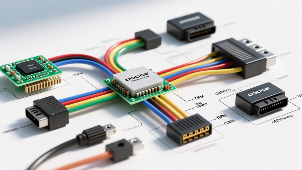
Introduction to the Dodge Challenger Electrical System
When you first open a factory Dodge Challenger wiring diagram, the sheer volume of multiplexed networks, solid-state relays, and module pinouts can be overwhelming. Whether you own an early 2008 LC-platform V6 or a modern supercharged Hellcat, understanding the fundamentals of Chrysler's electrical architecture is critical before you cut, splice, or probe a single wire. Modern Challengers rely heavily on the CAN (Controller Area Network) bus and a centralized power distribution system, meaning a simple mistake can cascade into multiple module failures.
This beginner-friendly guide breaks down the essentials of reading Chrysler schematics, understanding OEM wire color codes, and safely tracing common circuits like the OBD-II port and Uconnect infotainment system. By mastering these fundamentals, you will avoid the most common pitfalls that plague DIY automotive electrical work.
Decoding Chrysler LC Platform Schematics
Factory service manuals from Mopar TechAuthority use a standardized grid system to map out the vehicle. Unlike older point-to-point wiring diagrams, modern schematics are broken down by system (e.g., Exterior Lighting, CAN Bus, Engine Management) and utilize a grid coordinate system (like A1, B4) to help you trace a wire across multiple pages.
Key Symbols to Memorize
- Splice (S100, S200): Represented by a solid black dot where three or more lines intersect. This indicates wires are physically soldered and sealed together inside the harness.
- Ground (G100, G200): Represented by a symbol resembling an upside-down pitchfork. The number corresponds to a physical location map in the service manual (e.g., G200 is typically located on the left A-pillar or strut tower).
- Connectors (C100, C200): Denoted by a numbered box or plug shape. 'C' stands for Connector, and the number identifies the specific harness junction block.
The TIPM: A Beginner's Warning
The most critical component in any 2008+ Dodge Challenger is the Totally Integrated Power Module (TIPM). Located in the engine bay, the TIPM replaces the traditional fuse box and many functions of the Body Control Module (BCM). It houses standard fuses, but more importantly, it utilizes solid-state relays and microprocessors to control high-current circuits like fuel pumps, cooling fans, and exterior lighting.
Real-World Failure Mode: Many beginners attempt to upgrade their halogen headlights to LEDs by simply splicing into the headlight harness or swapping the bulb. The TIPM monitors the current draw (Amperage) of the lighting circuits. Because LEDs draw significantly less current than halogen bulbs, the TIPM assumes the bulb is blown. It will then trigger a 'Lamp Out' warning on the dash and may pulse the circuit (PWM) or cut power entirely to prevent a perceived short circuit. Always use CAN-bus compatible LED drivers or properly rated load resistors when modifying TIPM-controlled circuits.
OEM Wire Color Codes & AWG Specifications
Chrysler uses a two-tone color coding system for the majority of its wiring harness. The first color listed is the base insulation color, and the second is the tracer or stripe. For example, DK GN/OR means Dark Green with an Orange stripe. Understanding wire gauge (AWG) is equally important to prevent voltage drop and electrical fires.
| Circuit Type | Typical AWG Size | Common Challenger Colors | Application Example |
|---|---|---|---|
| CAN Bus Network | 18 - 20 AWG | White (High), White/Black (Low) | OBD-II Port, Uconnect Radio, PCM |
| Sensor / Signal | 20 - 22 AWG | Dark Green/Orange, Gray/Black | O2 Sensors, MAP Sensor, MAF |
| Standard Lighting | 16 - 18 AWG | White/Tan, Dark Green/White | Tail lights, Turn signals, License plate |
| High Current / Power | 10 - 12 AWG | Pink/Red, Black/Light Blue | Main IGN feeds, Fuel Pump, Amp power |
| Heavy Grounds | 8 - 10 AWG | Solid Black | Engine Block to Chassis, Battery to TIPM |
Beginner Project 1: Tracing the OBD-II Port
The On-Board Diagnostics (OBD-II) port is your gateway to the Challenger's CAN bus network. Whether you are plugging in a basic code reader, installing a performance tuner like a DiabloSport, or logging data with HP Tuners, knowing the pinout is essential for diagnosing communication faults (like the dreaded U0100 'Lost Communication with ECM' code).
According to the SAE J1962 Standard, the physical connector shape is universal, but the pin assignments vary by manufacturer. Below is the standard Chrysler CAN-bus pinout found in the LC-platform Challenger:
| Pin Number | Function | Wire Color (Typical) | Voltage / Notes |
|---|---|---|---|
| 4 | Chassis Ground | Black | 0.0V (Must have continuity to battery negative) |
| 5 | Signal Ground | Black/Light Green | 0.0V (Dedicated ground for module logic) |
| 6 | CAN High (C-Bus) | White | 2.5V - 3.5V (Idle / Recessive state) |
| 14 | CAN Low (C-Bus) | White/Black | 1.5V - 2.5V (Idle / Recessive state) |
| 16 | Battery Power (B+) | Pink or Pink/Red | 12.0V - 14.4V (Constant hot, fused at TIPM) |
Pro Tip: If your scanner will not power on, check Pin 16 for 12V and Pin 4 for continuity to ground. If the scanner powers on but won't link to the PCM, use a Digital Multimeter (DMM) to check for 60 Ohms of resistance between Pin 6 and Pin 14 (with the battery disconnected). This verifies the CAN bus terminating resistors are intact.
Beginner Project 2: Uconnect Radio Harness Basics
Upgrading the audio system or installing a backup camera is a common first mod for Challenger owners. However, modern Uconnect systems do not use traditional 'switched 12V' (red) and 'constant 12V' (yellow) wires in the same way older cars did. The radio is often 'woke up' via a CAN bus message from the BCM when the ignition is turned on.
Standard 430N / 8.4 Uconnect Pinout Reference
- Pink/White: Constant 12V Battery Feed (Fused)
- White/Red or Dark Blue/White: Fused Ignition Switch Output (RUN/ACC)
- Black/Light Green: Main Logic Ground
- White & White/Black: CAN High / CAN Low (Used for steering wheel controls, dimming, and BCM wake-up signals)
Warning: Never splice into the CAN High or CAN Low wires to power aftermarket accessories. The CAN bus operates on highly sensitive millivolt differential signaling. Adding aftermarket loads will corrupt the network, potentially causing the transmission to enter limp mode or the airbag light to illuminate. Always use a T-harness or a dedicated CAN-bus interface module (like a Maestro RR or PAC RP4-CH11) to translate data signals into standard 12V analog outputs.
Essential Tools & Safe Probing Techniques
To successfully navigate a Dodge Challenger wiring diagram and test circuits, you need the right tools. Avoid using cheap test lights on modern Chrysler vehicles; an incandescent test light draws too much current and can fry sensitive PCM driver circuits or trigger TIPM fault codes.
The Right Way to Probe Connectors
Modern Challengers use weather-sealed connectors (like the TE Connectivity AMP and Molex MX150 series). These connectors feature silicone grommets that keep moisture out. Never pierce the wire insulation with a T-pin or needle to test for voltage. Piercing the insulation creates a micro-hole where copper corrosion will begin immediately, leading to high-resistance faults months down the road.
Instead, use back-probing pins designed specifically for automotive diagnostics. Insert the fine back-probe into the rear (wire side) of the connector until it gently makes contact with the metal terminal inside, allowing you to read voltage with your DMM without compromising the weather seal.
Grounding Best Practices for Aftermarket Accessories
According to Haynes Chrysler Repair Manuals, over 70% of automotive electrical gremlins are caused by poor grounds. If you are adding an aftermarket amplifier, fuel pump, or auxiliary lighting, do not simply bolt a ring terminal to a random seatbelt bolt or strut tower nut.
- Find a Factory Ground: Look for existing ground studs (usually marked with a ground symbol) on the chassis or engine block.
- Remove Paint and Clearcoat: The Challenger's chassis is heavily coated in paint and undercoating, which act as insulators. Use a wire wheel or sandpaper to expose bare, shiny metal at the grounding point.
- Use Star Washers: Place a steel star lock washer between the ring terminal and the bare metal. The teeth of the washer bite into the metal, ensuring a vibration-proof, low-resistance connection.
- Protect Against Corrosion: Once torqued down, coat the entire ground connection with dielectric grease or battery terminal protector spray to prevent galvanic corrosion.
Conclusion
Learning to read a Dodge Challenger wiring diagram is a foundational skill that will save you hundreds of dollars in diagnostic fees and prevent catastrophic module damage. By respecting the TIPM's current-sensing capabilities, utilizing proper back-probing techniques, and understanding the nuances of Chrysler's CAN bus network, you can confidently tackle everything from basic sensor replacements to complex audio upgrades. Always verify your specific model year and trim level against factory service documentation before making permanent modifications to your vehicle's electrical system.