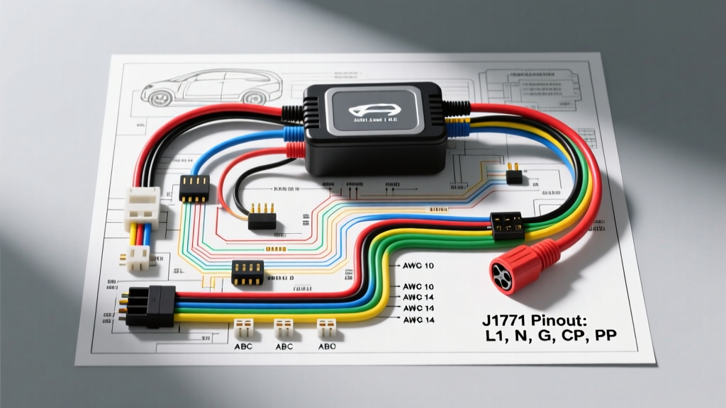
Understanding the EV Wiring Diagram for 220v Level 2 Architecture
When transitioning from internal combustion engine (ICE) diagnostics to electric vehicle (EV) high-voltage systems, technicians must completely reframe their understanding of automotive electrical architecture. While standard vehicle networks operate on 12V or 24V DC, the Level 2 charging infrastructure necessitates a specialized wiring diagram for 220v AC integration. This alternating current is routed directly from the Electric Vehicle Supply Equipment (EVSE) through the J1772 charge port and into the vehicle's Onboard Charger (OBC). The OBC is responsible for rectifying the 220v AC into high-voltage DC (typically 400V or 800V) to replenish the main traction battery. Understanding the precise routing, wire gauges, and control signal logic outlined in the OEM wiring diagram for 220v is critical for diagnosing charging faults, replacing the OBC, or integrating aftermarket shore-power systems in custom EV conversions and electric RVs.
SAE J1772 to OBC Pinout and Signal Routing
The cornerstone of any North American 220v Level 2 charging wiring diagram is the SAE J1772 connector interface. Unlike a simple 12V DC circuit that only requires power and ground, the 220v AC EV charging circuit utilizes five distinct pins to manage power delivery, safety interlocks, and pulse-width modulation (PWM) communication. The AC Line 1 (L1) and AC Line 2 (L2) pins deliver the split-phase 220v/240v AC power. However, the vehicle's OBC will not close its internal AC contactors to accept this 220v power until it validates the Control Pilot (CP) and Proximity Pilot (PP) signals.
| Pin | Function | Typical OEM Wire Color | Signal / Voltage Spec |
|---|---|---|---|
| 1 | AC Line 1 (L1) | Black / Red | 220v - 240v AC |
| 2 | AC Line 2 (L2) | White / Black | 220v - 240v AC |
| 3 | Protective Earth (Ground) | Green / Yellow-Green | 0v Reference |
| 4 | Control Pilot (CP) | Blue / Shielded | +12v / -12v 1kHz PWM |
| 5 | Proximity Pilot (PP) | Orange / Shielded | Resistive Voltage Divider |
AC Input Wire Gauge (AWG) and Insulation Specifications
Routing 220v AC from the charge port inlet to the OBC requires strict adherence to automotive high-current wire gauge standards. Because Level 2 charging can sustain continuous loads of 32A to 48A for several hours, the National Electrical Code (NEC) and SAE automotive standards dictate that the wiring must be rated for 125% of the continuous load. Therefore, a 40A charging circuit requires wire rated for at least 50A. In most OEM wiring diagrams for 220v EV applications, you will find 6 AWG or 4 AWG cross-linked polyethylene (XLPE) insulated copper wire. Standard PVC insulation is insufficient due to the high ambient temperatures in the engine bay or undercarriage where the OBC is typically mounted.
| OBC Max AC Current | Minimum Wire Gauge (AWG) | Insulation Rating | Terminal Torque Spec |
|---|---|---|---|
| 32 Amps (7.6 kW) | 8 AWG | XLPE 125C | 4.5 Nm |
| 40 Amps (9.6 kW) | 6 AWG | XLPE 125C | 6.0 Nm |
| 48 Amps (11.5 kW) | 4 AWG | XLPE 125C | 8.5 Nm |
| 80 Amps (19.2 kW) | 2 AWG or 1/0 AWG | Silicone / XLPE 150C | 12.0 Nm |
Internal OBC Architecture: EMI Filtering and Rectification
Once the 220v AC passes the main contactors and HVIL safety checks, it enters the internal circuitry of the Onboard Charger. The first stage of the OBC, as depicted in detailed OEM schematics, is the Electromagnetic Interference (EMI) filter. This stage utilizes common-mode chokes and X/Y capacitors to prevent high-frequency switching noise generated by the OBC from feeding back into the local 220v power grid. Following the EMI filter, the AC current passes through a bridge rectifier, converting the 220v AC into rough DC. This is immediately smoothed by a Power Factor Correction (PFC) boost converter, which elevates the DC bus voltage to approximately 400V while ensuring the AC current draw remains perfectly in phase with the AC voltage waveform. Troubleshooting a dead OBC often begins with checking the internal ceramic fuses located between the 220v AC input terminals and the EMI filter board.
Control Pilot (CP) and Proximity Pilot (PP) Diagnostics
The most complex aspect of the 220v charging diagram is the Control Pilot (CP) circuit. The EVSE generates a 1kHz square wave PWM signal that toggles between +12V and -12V. The vehicle's OBC monitors this signal to determine the maximum allowable current draw. By measuring the duty cycle of the PWM signal with an oscilloscope, a technician can verify the EVSE's advertised capacity. A 10% duty cycle indicates 6A, while a 53% duty cycle indicates 32A. If the OBC detects a duty cycle that exceeds its internal hardware limits, or if the signal voltage drops below the +9V threshold in State B (vehicle plugged in, not charging), the OBC will abort the 220v AC handshake and throw a diagnostic trouble code (DTC) such as P0D21 (EVSE Cord Fault).
The Proximity Pilot (PP) circuit acts as a physical safety interlock. It utilizes a resistive voltage divider network inside the J1772 connector. When the charging cable is fully inserted, a specific resistance (typically 150 ohms to 330 ohms, depending on the cable's current rating) is completed to ground. The OBC reads this resistance via a 5V reference pull-up. If the driver presses the release button on the J1772 handle, a microswitch opens the circuit, instantly signaling the OBC to open the main 220v AC contactors. This prevents dangerous 220v AC arcing at the connector pins. When troubleshooting a wiring diagram for 220v charging faults, always verify the PP resistance before condemning the OBC.
High-Voltage Interlock Loop (HVIL) Integration
Modern EVs also integrate the 220v AC input into the broader High-Voltage Interlock Loop (HVIL). The HVIL is a low-voltage (typically 5V or 12V) series circuit that passes through all high-voltage connectors, including the OBC AC and DC terminals. If the 220v AC inlet is loose, or if the OBC high-voltage DC output connector to the battery junction box is not fully seated, the HVIL circuit opens. The vehicle's Battery Management System (BMS) detects this open loop and disables the high-voltage contactors. When referencing the wiring diagram for 220v systems, trace the HVIL pins (usually labeled HVIL+ and HVIL-) to ensure continuity across the OBC harness connector.
Troubleshooting Decision Tree: 220v OBC Faults
- Symptom: Vehicle plugged in, but dashboard shows 'Check Charge System' and OBC refuses to close AC contactors.
Diagnostic Step: Measure CP signal at the OBC harness. If PWM is absent, fault is in the EVSE or J1772 cable. If PWM is present (e.g., 32% duty cycle) but OBC ignores it, check the CP ground return wire for high resistance. - Symptom: Charging initiates but aborts randomly after 10-15 minutes with OBC thermal DTC.
Diagnostic Step: Inspect the 220v AC L1 and L2 terminal connections at the OBC. Loose terminals cause micro-arcing and extreme localized heat. Verify torque specs match the OEM wiring diagram for 220v guidelines (typically 6.0 Nm for 6 AWG). Check the OBC liquid cooling loop for airlocks. - Symptom: 220v AC breaker on the EVSE trips immediately upon connection.
Diagnostic Step: Disconnect the OBC AC harness. Megger test (insulation resistance test) the L1 and L2 wires from the charge port to the OBC. A reading below 2 Megohms indicates chafed XLPE insulation grounding out to the chassis.
Summary and Authoritative References
Mastering the wiring diagram for 220v EV charging systems requires a hybrid approach, combining traditional residential AC electrical knowledge with advanced automotive CAN-bus and PWM diagnostics. Always consult the specific OEM service manual for exact pinouts, as wire colors and HVIL routing can vary significantly between manufacturers like Tesla, GM, and Ford. For foundational standards, refer to the SAE J1772 Recommended Practice and the US Department of Energy EV Infrastructure Guidelines. Furthermore, ensure all high-current wire gauge selections comply with the NFPA 70 National Electrical Code regarding continuous load derating. Proper adherence to these specifications ensures safe, efficient, and reliable high-voltage energy transfer.