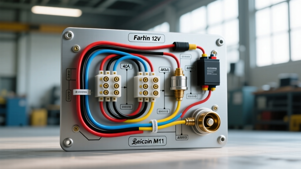
Understanding the Farbin Horn Wiring Diagram Architecture
Installing a Farbin dual-trumpet air horn system requires significantly more electrical infrastructure than simply splicing into your vehicle's existing factory horn circuit. Factory horn circuits are engineered for low-amperage electromagnetic disc horns, typically drawing between 5 to 10 amps and utilizing thin 18 AWG or 16 AWG wiring. In stark contrast, the Farbin 12V air compressor motor demands a dedicated high-amperage circuit to manage the massive inrush current generated during startup. This complete Farbin horn wiring diagram walkthrough details the exact relay logic, AWG wire sizing, circuit protection, and chassis grounding protocols required to safely integrate an aftermarket air compressor into your vehicle's electrical architecture without risking a harness fire, voltage drop, or PCM backfeed.
The Inrush Current Problem: Why Factory Wiring Fails
When an electric motor starts, it experiences a locked-rotor state for a fraction of a second before the armature begins spinning. During this microsecond window, the motor draws 'inrush current,' which can be 3 to 5 times higher than its continuous running amperage. A Farbin compressor that nominally draws 15 amps under load can easily spike to 45 amps upon initial engagement. If you wire the compressor directly to the factory steering wheel horn switch or the OEM horn relay output, the 18 AWG factory wiring will act as a resistor. This severe voltage drop will starve the compressor of amperage, resulting in a sluggish, low-decibel horn blast, while simultaneously generating enough thermal energy to melt the factory wire insulation and potentially ignite a dash fire. The solution is a remote-mounted, heavy-duty 12V 40A automotive relay triggered by the low-amperage factory switch.
Core Components of the Farbin Relay Circuit
To execute this wiring diagram correctly, you must source components that meet stringent automotive environmental standards. Do not use hardware store relays or marine-grade tinned wire, which lacks the high-temperature abrasion resistance required under the hood.
The 12V 40A Bosch-Style Relay (ISO 7588 Standard)
The heart of the Farbin horn wiring diagram is a standard 5-pin or 4-pin 12V 40A relay. We utilize a 4-pin configuration (Pins 30, 85, 86, and 87) as the 87a (normally closed) terminal is unnecessary for a horn application. Ensure the relay features an internal suppression resistor or diode if you are triggering it via a modern CAN-bus system or a solid-state Body Control Module (BCM) to prevent inductive flyback voltage from damaging the vehicle's logic boards.
Wire Insulation Standards: GXL vs. TXL
According to SAE J1128 specifications, automotive primary cable must withstand extreme under-hood temperatures and chemical exposure. For this build, specify GXL (General Cross-Linked) or TXL (Thin-wall Cross-Linked) wire. TXL is preferred for routing through the firewall due to its thinner insulation profile, while GXL offers superior abrasion resistance for engine bay routing. Avoid standard PVC-insulated wire, which becomes brittle and cracks at sustained temperatures above 105°C.
Step-by-Step Wiring Walkthrough
Follow this precise sequence to build the high-current and low-current sides of the circuit.
Phase 1: The High-Current Feed (Power to Load)
- Battery to Relay (Pin 30): Run a continuous length of 10 AWG TXL wire from the positive battery terminal to Pin 30 of the 40A relay. Install a 30A or 40A Littelfuse ATO/ATC blade fuse in an inline weatherproof holder within 6 inches of the battery positive post. This protects the entire harness in the event of a dead short.
- Relay to Compressor (Pin 87): Run a second length of 10 AWG wire from Pin 87 directly to the positive terminal on the Farbin air compressor. Use a closed-barrel, adhesive-lined heat shrink crimp terminal (ring terminal) to secure the wire to the compressor stud. The adhesive lining prevents moisture wicking and copper oxidation.
- Compressor Grounding: Do not rely on the compressor's mounting brackets for a ground path. Vibration and powder-coated brackets create high-resistance connections. Run a dedicated 10 AWG ground wire from the compressor's negative terminal directly to a clean, bare-metal chassis point or the engine block. Sand away all paint and primer, apply a dielectric grease after torquing the bolt to 15 lb-ft to prevent future corrosion.
Phase 2: The Low-Current Trigger (Switch to Coil)
- Switch Power Source: Locate the factory horn trigger wire at the steering column clock spring or the OEM horn relay. Using a digital multimeter, verify that this wire receives 12V only when the steering wheel horn pad is depressed.
- Relay Coil Power (Pin 86): Splice into the factory horn trigger wire using a solder-seal splice connector. Run a 16 AWG wire from this splice to Pin 86 on the relay. This provides the low-amperage signal to energize the relay coil.
- Relay Coil Ground (Pin 85): Run a 16 AWG wire from Pin 85 to a dedicated, clean chassis ground point. When the factory switch is pressed, 12V flows from Pin 86 through the internal copper coil to Pin 85 (ground), creating an electromagnetic field that pulls the internal contactor closed, bridging Pin 30 and Pin 87 to fire the compressor.
Wire Gauge (AWG) and Circuit Protection Specifications
The following table outlines the exact specifications required for a safe, voltage-drop-compliant Farbin horn installation. These values assume a standard 15-foot total round-trip wire length from the battery to the relay, and from the relay to the compressor.
| Circuit Segment | Function | Wire Gauge (AWG) | Wire Type | Protection / Fuse |
|---|---|---|---|---|
| Battery to Relay (Pin 30) | Main High-Current Feed | 10 AWG | Red GXL/TXL | 40A Inline ATO Fuse |
| Relay (Pin 87) to Compressor | Load Delivery | 10 AWG | Red GXL/TXL | Protected by Main Fuse |
| Compressor to Chassis | High-Current Ground | 10 AWG | Black GXL/TXL | N/A (Ensure bare metal) |
| Factory Switch to Relay (86) | Coil Trigger Signal | 16 AWG | Blue TXL | Factory Fuse Panel |
| Relay (Pin 85) to Chassis | Coil Ground | 16 AWG | Black TXL | N/A (Ensure bare metal) |
Advanced Troubleshooting: Voltage Drop and Duty Cycle Limits
Even with a flawless physical installation, Farbin air horn systems can suffer from performance degradation if electrical parameters are ignored. If your horn sounds weak or the compressor stalls, perform a live voltage drop test.
Performing a Live Voltage Drop Test
Set your multimeter to DC Volts. Place the red probe on the battery positive post and the black probe on the compressor's positive stud while an assistant holds the horn button. A healthy circuit will show a voltage drop of less than 0.5V (meaning the compressor is receiving at least 12.1V on a running 12.6V system). If the drop exceeds 1.0V, you have excessive resistance. This is almost always caused by undersized wire, a corroded inline fuse holder, or a failing relay contactor. Replace the relay and inspect all crimp connections.
Understanding Compressor Duty Cycle Restrictions
The Farbin 12V compressor is an intermittent-duty motor, typically rated for a 15% duty cycle. This means for every 60 seconds of operation, the motor requires at least 45 seconds of cooling time. If you install this system on a vehicle used for train-horn pranks or prolonged signaling, the motor windings will overheat, melting the internal varnish insulation and causing a dead short. If continuous operation is required, you must upgrade to a 100% duty-cycle VIAIR or Thomas continuous-duty compressor and upgrade the main power feed to 8 AWG wire with a 60A fuse.
Air Line Routing vs. Electrical Harness Isolation
When routing the physical harness alongside the polyurethane air lines to the dual trumpets, maintain a minimum 4-inch separation from exhaust manifolds and sharp steering linkages. Secure the 10 AWG wiring in split-loom corrugated tubing, and use UV-resistant zip ties anchored to existing factory wire looms. Never zip-tie air lines directly to electrical wires; vibration will cause the hard plastic air line to saw through the wire insulation over time, resulting in a dead short to ground and a blown 40A main fuse. Always route the air lines through dedicated grommets when passing through the firewall or core support to prevent chafing and subsequent air leaks that would force the compressor to cycle more frequently, reducing its operational lifespan.