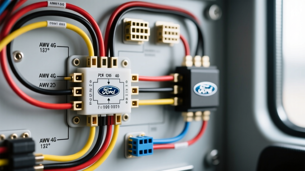
Introduction to the Ford 4G Smart Charge Architecture
The evolution of automotive electrical networks transitioned from simple, mechanically regulated alternators to highly integrated, computer-controlled power management systems. When analyzing the wiring diagram charging system for the Ford 4G alternator (widely deployed in late 1990s through mid-2000s F-150, Mustang, and Crown Victoria platforms), technicians must understand that the alternator is no longer an isolated component. It is a peripheral device managed by the Powertrain Control Module (PCM). The Ford Smart Charge system dynamically adjusts target voltage between 13.5V and 15.0V based on Intake Air Temperature (IAT), Engine Coolant Temperature (ECT), and battery thermal sensors. This advanced technical deep dive dissects the OEM wiring topology, circuit pinouts, and diagnostic strategies required to accurately troubleshoot 4G charging anomalies without resorting to unnecessary parts replacement.
Decoding the Wiring Diagram Charging System Topology
A common failure mode in late-model Ford trucks is an overcharging or undercharging condition stemming from a misunderstanding of the 4G regulator harness. Unlike older 1-wire or 2-wire setups, the 4G wiring diagram charging system utilizes a dedicated 3-pin connector interfacing directly with the internal voltage regulator. This harness dictates the excitation current, battery sense feedback, and stator monitoring. If the PCM detects an open circuit in the sense wire, it defaults to a fail-safe voltage of approximately 13.5V, which may be insufficient to maintain a deeply discharged battery under heavy accessory loads. Understanding the exact routing and termination of these three circuits is critical for passing SAE J180 electrical compliance standards during aftermarket modifications or harness repairs.
Stator, Rotor, and Internal Regulator Mapping
The internal regulator of the 4G alternator relies on the stator tap to verify that the alternator is physically spinning and generating AC voltage before it fully engages the rotor field. This prevents the regulator from draining the battery if the ignition is left in the 'ON' position with the engine off. The stator wire (S-circuit) routes directly from the internal stator windings to the regulator pigtail. It is strictly an internal feedback loop on most 4G applications, but verifying its continuity at the regulator plug is a mandatory step when diagnosing a 'no-charge' condition where the B+ output reads exactly 12.6V at idle.
PCM Pinout and Connector Specifications
The 3-pin regulator connector is the nerve center of the 4G system. Below is the definitive reference chart for the OEM wire colors, AWG specifications, and voltage expectations for a standard 5.4L Triton V8 application. Always verify against your specific vehicle's EVTM (Electrical and Vacuum Troubleshooting Manual) as mid-year running changes can alter wire striping.
| Pin | Circuit Name | OEM Wire Color | AWG | Function & Logic | KOEO Voltage | KOER Voltage |
|---|---|---|---|---|---|---|
| 1 | I (Ignition/Lamp) | Light Green/Red | 18 | Provides initial rotor excitation and interfaces with the PCM-controlled instrument cluster warning lamp. | 0.0V - 2.0V | 12.5V - 14.5V |
| 2 | A (Sense/Battery) | Yellow/White | 18 | Direct battery voltage sense. Regulator adjusts duty cycle based on this exact reading to compensate for voltage drop. | 12.2V - 12.6V | 13.5V - 15.0V |
| 3 | S (Stator) | White/Black | 18 | Stator tap feedback. Proves alternator rotation and internal AC generation to the regulator logic board. | 0.0V | 6.0V - 8.0V (AC) |
PCM Excitation and Instrument Cluster Logic
The 'I' circuit is frequently misdiagnosed. In the Ford Smart Charge architecture, the PCM does not simply send a 12V signal to turn the alternator on. Instead, the PCM provides a switched ground path to the instrument cluster charge indicator lamp. When the key is ON and the engine is OFF (KOEO), the PCM grounds the circuit, illuminating the lamp and allowing a small excitation current (approx. 250mA) to flow through the bulb and into the alternator's 'I' pin. This initial current 'wakes up' the rotor field. Once the engine starts and the stator tap (S-circuit) confirms rotation, the internal regulator takes over, pushing system voltage back out through the 'I' pin. The PCM senses this voltage rise, removes the ground path, and the lamp extinguishes. If the bulb is burnt out, or if an LED conversion has been performed without a parallel resistor, the alternator will fail to excite, resulting in a dead battery despite a perfectly functional alternator.
Wire Gauge (AWG) and Current Carrying Requirements
The B+ output circuit on a 135A 4G alternator requires heavy-gauge cabling to prevent thermal degradation and excessive voltage drop. Ford typically utilizes a 4 AWG or 2 AWG cable (Circuit 36, often Black/Orange) routed from the alternator B+ stud to the starter motor solenoid or a dedicated mega-fuse junction block. According to AutoShop 101 electrical fundamentals, a 4 AWG copper wire is rated for approximately 85A to 95A in a high-temperature engine bay environment. Because the 4G can peak at 135A, the OEM relies on the fact that the alternator rarely operates at maximum continuous output. However, when upgrading to high-draw aftermarket audio or lighting, upgrading the B+ cable to 1/0 AWG welding cable and adding a parallel 1/0 AWG ground from the alternator casing to the engine block is mandatory to maintain SAE J1113 electromagnetic compatibility and prevent PCM interference.
Voltage Drop Testing the B+ and Sense Circuits
The 'A' (Sense) circuit is an 18 AWG wire that routes directly to the positive battery terminal or the main junction block. Its sole purpose is to measure the exact voltage at the battery posts. If the B+ cable is corroded, it may drop 1.5V under load. If the sense wire is intact, the regulator sees the low voltage at the battery and increases the rotor field duty cycle, pushing the B+ terminal voltage up to 15.5V to compensate, ensuring the battery still receives 14.0V. Conversely, if the 18 AWG sense wire is broken or has high resistance, the regulator defaults to measuring voltage internally at the alternator casing. It will limit output to 13.5V, and after the 1.5V drop across the corroded B+ cable, the battery only receives 12.0V, leading to chronic undercharging. Always perform a voltage drop test: place the multimeter positive lead on the alternator B+ stud and the negative lead on the battery positive post. With the engine running and loads applied, the drop must not exceed 0.2V.
Oscilloscope Diagnostics: AC Ripple and Diode Trio Analysis
Multimeters average voltage over time, masking critical failures in the rectifier bridge. When consulting the wiring diagram charging system for intermittent electrical gremlins (such as ABS module dropouts or erratic transmission shifting), an automotive oscilloscope is required. Connect the scope to the B+ terminal and set it to AC coupling. A healthy 4G alternator should exhibit an AC ripple voltage of less than 100mV (0.1V) at 2000 RPM. If the ripple exceeds 250mV, or if the waveform shows a missing hump (indicating a blown diode in the rectifier trio), the alternator is injecting destructive AC noise into the vehicle's CAN-bus and PCM reference circuits. Pico Technology's waveform library provides excellent baseline captures for identifying specific diode failure signatures before they trigger a hard charging system DTC.
Advanced Diagnostic Decision Tree: Smart Charge Failures
Use this structured decision tree to isolate faults within the Ford 4G Smart Charge network before condemning the alternator or PCM.
- Symptom: Battery Warning Lamp ON, Alternator Output at 12.6V (No Charge).
- Step 1: Check B+ fuse and 4 AWG cable continuity. If OK, proceed.
- Step 2: Verify 12V at the 'I' pin (Light Green/Red) with KOEO. If 0V, check instrument cluster bulb and PCM ground circuit.
- Step 3: If 'I' pin has 12V KOEO, check 'S' pin (White/Black) for internal stator continuity. If open, replace alternator.
- Symptom: Overcharging (15.5V+), Battery Gassing, Headlights Pulsing.
- Step 1: Measure voltage at the 'A' pin (Yellow/White). If it reads 0V or significantly lower than battery post voltage, the sense wire is open.
- Step 2: Repair the 18 AWG Yellow/White sense wire to the battery positive terminal.
- Symptom: PCM DTC P0562 (System Voltage Low) or P0563 (System Voltage High).
- Step 1: Connect scan tool and monitor PCM PID 'Desired Generator Voltage' vs 'Actual Generator Voltage'.
- Step 2: If Desired is 14.5V but Actual is 12.6V, perform AC ripple test. High ripple indicates internal regulator/rectifier failure despite correct external wiring.
References and Authoritative Standards
Accurate diagnosis of modern charging networks requires adherence to OEM engineering standards. The diagnostic procedures and circuit topologies detailed above are derived from Ford Motor Company EVTM schematics and SAE International technical papers regarding automotive electrical load management and Smart Charge pulse-width modulation protocols. Always consult the specific year's factory service manual for exact pinout variations, as mid-year harness revisions are common in high-volume production platforms.