The Hidden Dangers of Misinterpreting Power Window Schematics
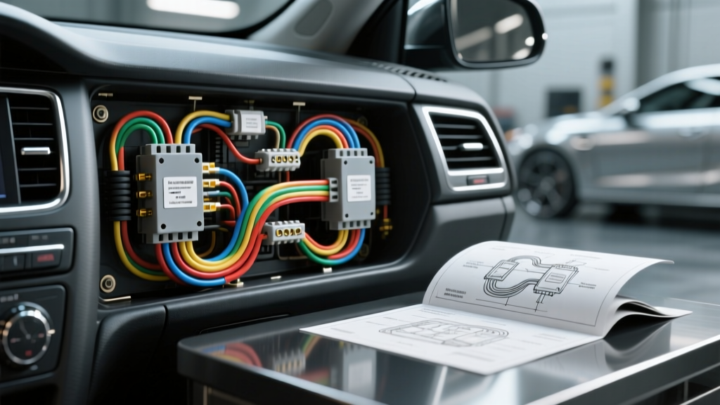
When installing, repairing, or bypassing OEM controls, consulting a wiring diagram for electric window switch applications is mandatory. However, misinterpreting these schematics is one of the leading causes of melted harnesses, blown main fuses, and even vehicle fires in aftermarket and DIY repair scenarios. Power window motors are high-torque, high-draw inductive loads. They do not behave like simple resistive circuits (such as headlights or horn relays). When the glass reaches the top or bottom of the track, the motor stalls, causing a massive spike in amperage. This guide outlines the most critical mistakes automotive technicians and DIYers make when reading and executing window switch wiring diagrams, alongside the strict safety protocols required to prevent catastrophic electrical failures.
Standard 5-Pin Switch Architecture and Pinout Reference
Before identifying mistakes, you must understand the internal architecture of the switch. Most standard 5-pin switches (widely used in GM trucks, older Ford passenger cars, and universal hot-rod kits) utilize a Double Pole, Double Throw (DPDT) center-off internal relay structure. This design reverses the polarity sent to the DC window motor without requiring external relays. Misunderstanding this internal crossover is where most wiring errors begin.
| Pin | Function | Typical GM Wire Color | Min. AWG | Engineering Notes |
|---|---|---|---|---|
| 1 | 12V+ Battery Feed | Red / Orange | 12 AWG | Must be fed via a 30A auto-resetting breaker. |
| 2 | Motor Output A (Up) | Dark Blue | 14 AWG | Carries +12V in Up, Ground in Down. |
| 3 | Motor Output B (Down) | Light Blue | 14 AWG | Carries Ground in Up, +12V in Down. |
| 4 | Chassis Ground | Black | 12 AWG | Completes the motor return circuit. |
| 5 | Illumination + | Brown / Gray | 18 AWG | Switched 12V+ from headlight circuit. |
Top 5 Fatal Mistakes When Reading the Wiring Diagram
1. Undersizing the Main Power Feed Wire
The most common and dangerous mistake is ignoring wire gauge specifications. A window motor draws roughly 6 to 8 amps during normal operation, but stall current (when the window hits the track limit) can spike to 22-25 amps for several hundred milliseconds. Many DIYers look at a wiring diagram for electric window switch circuits, see an 8-amp running draw, and mistakenly use 16 AWG primary wire. According to the SAE J1128 Low Tension Primary Cable Standard, 16 AWG wire is only rated for roughly 18 amps in a single-cable conduit. When the motor stalls, the 16 AWG wire acts as a resistive heating element, melting the PVC insulation and potentially igniting nearby carpeting or door panel sound deadening. Correction: Always use a minimum of 12 AWG stranded copper for the main 12V+ feed and the main chassis ground.
2. Using Standard Blade Fuses Instead of Circuit Breakers
Standard ATO/ATM blade fuses are designed to blow during a sustained overcurrent event. If you place a 20A or 30A blade fuse on the main power feed of a window switch, the natural stall current spike at the end of the window's travel will fatigue the fuse element. Over time, or during cold weather when the window tracks are stiff and draw more amperage, the fuse will blow under normal operating conditions. Correction: OEM wiring diagrams utilize an auto-resetting thermal circuit breaker (typically 30A) located in the fuse block or inline near the battery. This breaker trips during the stall spike and resets the moment the switch is released and the heat dissipates.
3. Misrouting the Illumination Ground (Backfeeding)
Pin 5 provides 12V+ for the switch's internal LED or incandescent bulb. The bulb completes its circuit by grounding through the switch housing or a dedicated 18 AWG ground wire. A frequent mistake is tying this delicate 18 AWG illumination ground into the heavy 12 AWG motor ground bus. If the main motor ground becomes corroded or loose, the high-draw motor current will seek the path of least resistance: it will backfeed through the 18 AWG illumination wire, instantly vaporizing it and potentially frying the vehicle's headlight switch or BCM (Body Control Module).
4. Ignoring Polarity Reversal Logic
Novices often assume a window switch simply 'sends power' to the motor. In reality, the motor is permanently grounded and permanently hot in some modern multiplexed systems, OR the switch acts as a crossover ground return in older systems. If you are adapting a universal 5-pin switch to a modern vehicle that uses a dedicated Window Control Module (like late-model GM or Ford LIN-bus systems), wiring the switch outputs directly to the motor will bypass the module's anti-pinch safety logic and auto-up/down features, creating a severe safety hazard.
5. Poor Terminal Crimping on Weather-Pack Connectors
When repairing a melted pigtail, technicians often reuse the old connector housing but fail to properly crimp the new terminals. Delphi (now Aptiv) Weather-Pack and Metri-Pack terminals require a specific ratcheting crimp tool. Using slip-joint pliers crushes the terminal wings unevenly, creating a high-resistance connection. Under the 20A load of a window motor, this high-resistance joint will generate excessive heat, melting the connector face. Always use a proper crimping tool and seal the connection with adhesive-lined heat shrink tubing.
Critical Safety Warnings Before You Cut or Splice
- Disconnect the Battery: Always disconnect the negative battery terminal and wait 5 minutes before cutting into any door harness. Modern doors contain side-impact airbag modules (often identified by yellow wiring looms). Piercing a yellow wire or shorting an airbag circuit can cause catastrophic deployment.
- Avoid Soldering in Flex Zones: Never solder splices in the wiring boot that connects the vehicle body to the door hinge. This area undergoes thousands of articulation cycles. Soldered joints become brittle and will fracture. Use only high-quality, adhesive-lined butt crimps rated for automotive use.
- Check for Pinched Wires: Before reinstalling the door panel, ensure the window regulator scissors do not intersect the wiring path. A severed 12V+ wire shorting against the metal door frame will cause immediate sparks and harness damage if the breaker fails to trip in time.
Real-World Troubleshooting: The Voltage Drop Test
If your windows are rolling up slowly or the switch feels hot to the touch, do not immediately replace the motor. The Haynes Power Window Diagnostics Guide highly recommends performing a voltage drop test under load. Set your digital multimeter to DC Volts. Place the red probe on the 12V+ battery post and the black probe on the output pin of the switch while an assistant holds the switch in the 'Up' position. A reading higher than 0.2V indicates excessive resistance in the power feed (likely a corroded breaker or undersized wire). Next, test the ground side by placing the red probe on the switch ground pin and the black probe on the negative battery post. High resistance here confirms a poor chassis ground, which is responsible for over 80% of slow-window complaints. Clean the ground ring terminal with a wire brush and apply dielectric grease to prevent future oxidation.