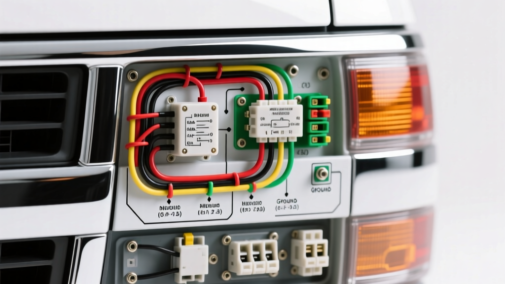
Introduction to the Automotive Wiring Diagram
For beginners and seasoned mechanics alike, finding a reliable wiring diagram automotive resource is the critical first step in diagnosing electrical gremlins. An automotive schematic is not just a drawing; it is a precise map of electron flow, component logic, and physical hardware. Unlike a simple mechanical linkage, electrical circuits rely on invisible voltage and current. To master vehicle electrics, you must learn to translate 2D symbols into 3D physical components hiding behind dashboards and inside engine bays.
In this foundational guide, we will decode a real-world circuit: the 1999-2006 GM GMT800 (Silverado/Sierra) Headlight and Daytime Running Light (DRL) system. This platform is notorious for headlight switch failures and ground corrosion, making it the perfect case study for learning how to trace power, understand relay logic, and use a digital multimeter (DMM) effectively.
Case Study: The GMT800 Headlight Circuit Architecture
The GMT800 headlight system does not route high-amperage headlight current directly through the dashboard switch. Doing so would melt the switch contacts and require massive, expensive wiring harnesses behind the dash. Instead, GM utilizes a low-amperage control circuit to trigger a high-amperage relay. Understanding this separation of 'control' and 'load' is the most important fundamental concept in modern automotive electrics.
The Anatomy of the Schematic Symbols
When you pull up the factory GM service manual schematic, you will see specific standardized symbols:
- Splice Pack (SP): Represented by a solid black dot where wires intersect. This indicates a physical, soldered, or crimped connection in the harness.
- Ground (GND): Denoted by a zig-zag line or a standard ground symbol, usually followed by a location code (e.g., G103 for Left Front Ground).
- Relay Coil vs. Relay Switch: The coil is drawn as a loop or box, while the internal switch is drawn as a hinged lever.
Understanding Relay Logic: The Bosch-Style Standard
The GMT800 uses a standard ISO/Bosch-style 4-pin mini relay for the main headlamp feed. Relays are electromagnetic switches. When 12V is applied to the coil, it creates a magnetic field that pulls a metal contact closed, allowing high current to flow to the headlights.
| Relay Pin | Standard Function | GMT800 Headlight Application | Wire Gauge / Color |
|---|---|---|---|
| 30 | Constant Battery Power (Load In) | Fused 12V from Underhood Fuse Block | 12 AWG / Red |
| 87 | Switched Power Out (To Load) | Feed to Headlamp Splice Pack | 14 AWG / Yellow |
| 85 | Relay Coil Ground | Chassis Ground | 18 AWG / Black |
| 86 | Relay Coil Switched 12V (Control) | Signal from Headlamp Switch | 18 AWG / Brown |
Pro Tip: If you are ever unsure which pin is which on an unmarked relay, use your multimeter's continuity setting. Pins 85 and 86 will show a resistance reading (typically 60-120 ohms) because they are the copper windings of the coil. Pins 30 and 87 will show 'OL' (Open Loop) until the relay is energized.
Decoding GM Wire Colors and Gauge Sizes
Wire color codes are the DNA of the harness. While aftermarket harnesses vary, OEM manufacturers adhere to strict color and gauge standards. According to SAE International J1128 standards for low-tension primary wire, the gauge (AWG) dictates the current-carrying capacity. Headlights draw significant current (typically 5-8 amps per low-beam bulb, up to 15 amps for high beams), requiring thicker wires to prevent voltage drop and heat buildup.
GMT800 Headlight Wire Specification Chart
| Circuit Path | OEM Wire Color | AWG Size | Expected Amperage |
|---|---|---|---|
| Battery to Relay (Pin 30) | Red | 12 AWG | 25A (Max Capacity) |
| Relay to Left Headlamp | Yellow | 14 AWG | 10A - 15A |
| Relay to Right Headlamp | Dark Green | 14 AWG | 10A - 15A |
| Headlamp Grounds (G103/G104) | Black | 14 AWG | 10A - 15A |
| Switch to Relay Coil (Pin 86) | Brown | 18 AWG | < 1A |
Connector Hardware: The Aptiv Metri-Pack 280
You cannot troubleshoot a wiring diagram without understanding the physical connectors joining the wires. The GMT800 platform heavily relies on the Aptiv Metri-Pack 280 series connectors for the headlamp pigtails.
The '280' refers to the width of the male terminal blade (2.8mm). These connectors feature a primary lock (the plastic housing) and a secondary lock (a red or yellow plastic wedge inserted after the terminals are seated). When diagnosing a dead headlight, a common beginner mistake is probing the back of the connector and pushing the terminal out of the housing because the secondary lock was missing or broken. Always inspect the TPA (Terminal Position Assurance) lock before back-probing.
Step-by-Step: Tracing the Circuit with a Multimeter
Let us assume the driver's side (Left) low beam is inoperative, but the passenger side works. Here is how you use the wiring diagram to diagnose the fault logically, moving from the simplest test to the most complex.
- Verify the Bulb and Fuse: Swap the left bulb to the right side. Check the underhood 'HEADLAMP' fuse with your DMM set to DC Volts. You should read 12.0V on both test points of the fuse with the switch ON.
- Test for Power at the Load: Unplug the Left Headlamp Metri-Pack connector. Turn the headlights ON. Probe the Yellow wire terminal in the harness side. If you read 12.0V+ (battery voltage), the relay, fuse, and feed wire are perfectly fine.
- Test the Ground Path: If you have 12V on the Yellow wire, the issue is the ground. Leave the DMM positive lead on the battery positive terminal. Move the negative lead to the Black wire terminal in the headlamp harness connector. You should read full battery voltage (12.0V+). If you read 0V, the Black wire is broken between the connector and Ground G103.
- Perform a Voltage Drop Test: If the light is dim, do not just check for '12V'. A corroded ground might still pass 11.5V, which a basic test light will illuminate, but it lacks the amperage capacity to run the bulb brightly. Set your DMM to DC Volts. Place the positive probe on the battery negative post, and the negative probe on the metal base of the headlight bulb socket. Turn the lights ON. A reading above 0.2V indicates excessive resistance (corrosion) at G103.
Real-World Troubleshooting: Common GMT800 Failures
Armed with the schematic and an understanding of the hardware, you can anticipate common failure modes specific to this vehicle architecture:
- Headlamp Switch Melting: While the main headlights use a relay, the GMT800 headlamp switch directly routes current for the instrument panel illumination and some marker lights. Over time, the internal contacts carbon-track and melt the plastic pigtail. If your dash lights flicker when you wiggle the switch, replace the switch and the Metri-Pack pigtail immediately to prevent a harness fire.
- Ground G103/G104 Corrosion: The front headlamp grounds are bolted to the inner fender liner support bracket, an area highly exposed to road salt and water. Galvanic corrosion between the copper ring terminal and the steel bracket creates a high-resistance diode effect. The fix is to remove the bolt, sand the metal to bare steel, apply dielectric grease, and torque to 9 Nm (80 lb-in).
- DRL Relay Chatter: If the headlights flicker rapidly when the key is ON but the engine is OFF, the DRL control module or the DRL relay coil is failing. The BCM (Body Control Module) pulses the ground to the DRL relay in series with a resistor to run the high-beams at 50% duty cycle for Daytime Running Lights. A failing resistor block near the underhood fuse block will cause erratic relay operation.
Conclusion and Further Study
Mastering the wiring diagram automotive fundamentals requires shifting your mindset from 'replacing parts' to 'following the electrons'. By understanding the separation of control and load circuits, recognizing OEM wire colors and gauges, and respecting the physical realities of connectors like the Metri-Pack 280, you can diagnose any 12V automotive electrical fault with confidence.
For further technical reading on automotive electrical diagnostics, we highly recommend reviewing the AA1Car Wiring Diagram Guide and studying the SAE standards for primary cable insulation and voltage drop thresholds. Always remember: a wiring diagram is only as good as the technician holding the multimeter.