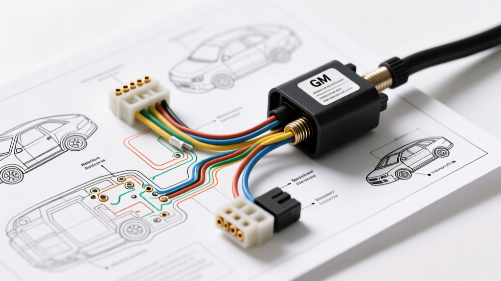
Understanding the GM 5-Wire MAF Sensor Circuit
Diagnosing a Mass Air Flow (MAF) sensor on modern General Motors vehicles requires more than just swapping parts. The GM 5-wire MAF configuration, standard on most LS and LT engines (including the 5.3L V8 Silverado, 6.2L Camaro, and Corvette), integrates both the MAF and Intake Air Temperature (IAT) sensors into a single housing. Unlike older analog voltage sensors, these modern Delphi and ACDelco units typically output a frequency-based square wave signal measured in Hertz (Hz). Misinterpreting this signal with a standard voltmeter is a leading cause of misdiagnosis. This guide provides a definitive GM MAF sensor wiring diagram reference and a step-by-step troubleshooting flow to isolate electrical faults, harness chafing, and ECM communication failures.
GM 5-Wire MAF/IAT Pinout and Wire Color Reference
Before probing the circuit, identify the specific pinout for the GM 5-pin Delphi connector (commonly found on GM part numbers like 12580415 or ACDelco 213-1677). The wire gauges are typically 20 AWG for signal circuits and 18 AWG for power and ground.
| Pin | Circuit Function | Typical GM Wire Color | Wire Gauge | Expected Value (KOEO) |
|---|---|---|---|---|
| A | IAT Signal (Analog) | Tan or Yellow | 20 AWG | 1.5V - 3.0V (Temp Dependent) |
| B | IAT Low Reference (Ground) | Black | 20 AWG | < 0.1V Voltage Drop |
| C | MAF Signal (Frequency) | Yellow or Tan/White | 20 AWG | 2,000 - 3,500 Hz (Idle) |
| D | Ignition 1 Voltage (Power) | Pink | 18 AWG | 12.2V - 12.6V (Battery Voltage) |
| E | MAF Low Reference (Ground) | Black/White | 20 AWG | < 0.1V Voltage Drop |
Step-by-Step MAF Wiring Troubleshooting Flow
Follow this sequential decision tree to isolate the root cause of MAF-related Diagnostic Trouble Codes (DTCs) such as P0101, P0102, P0103, or P0113. Always begin with the power supply and work your way toward the signal circuit.
Step 1: Visual Inspection and Connector Integrity
Before connecting a multimeter, perform a thorough physical inspection of the MAF pigtail and sensor housing.
- Check for Oil Contamination: If the vehicle uses an oiled aftermarket air filter (e.g., K&N), excess oil can coat the hot-wire element, insulating it and causing a false low-frequency reading (P0101). Clean with dedicated MAF cleaner only.
- Inspect Terminal Tension: Use a 0.64mm pin gauge to check the female terminals inside the connector. Loose terminals cause intermittent signal dropouts under engine vibration. If the pin slides in without resistance, the pigtail must be replaced.
- Harness Routing: Trace the harness 6 inches back from the connector. Look for chafing against the alternator bracket, throttle body, or intake manifold. GM Technical Service Bulletins (TSBs) frequently cite harness abrasion near the throttle body as a primary cause of P0102/P0103 codes.
Step 2: Verify Power Supply (Ignition 1 Voltage)
The MAF sensor requires a stable 12V reference to power its internal ASIC (Application-Specific Integrated Circuit) and heating element.
- Test Procedure: Set your Digital Multimeter (DMM) to DC Volts. Backprobe Pin D (Pink wire) at the harness connector with the Key On, Engine Off (KOEO). Connect the black DMM lead to a known good chassis ground.
- Decision Path A (12.2V - 12.6V Present): Power circuit is healthy. Proceed to Step 3.
- Decision Path B (0V or < 10V Present): You have an open or high-resistance fault in the Pink wire. Check the ENG IGN or ECM IGN fuse in the underhood fuse block. Perform a continuity test from the MAF Pin D to the fuse panel. If continuity is good, check for voltage drop across the fuse itself to rule out a corroded fuse terminal.
Step 3: Test Ground and Low Reference Circuits
GM utilizes dedicated 'Low Reference' circuits routed directly back to the ECM, rather than relying on a local chassis ground. This ensures the ECM can monitor the exact voltage potential of the sensor's ground.
- Test Procedure: Perform a voltage drop test on Pin B (IAT Ground) and Pin E (MAF Ground). Place the red DMM lead on the battery negative terminal and the black lead on the backprobed MAF ground pin (KOEO).
- Decision Path A (Voltage Drop < 0.1V): Ground circuits are intact. Proceed to Step 4.
- Decision Path B (Voltage Drop > 0.1V): High resistance exists in the ground wire. A voltage drop of 0.5V or higher on the MAF Low Reference (Pin E) will artificially inflate the MAF frequency signal, causing the ECM to inject too much fuel (running rich) and potentially setting a P0172 code alongside a P0101. Repair the Black/White wire or clean the ECM ground splice pack (typically located in the main engine harness).
Step 4: Signal Circuit Verification and Oscilloscope Testing
Because the GM MAF outputs a square wave frequency, a standard DMM in voltage mode will only show an 'average' voltage (usually around 2.5V), which is useless for diagnostics. You must measure Hertz (Hz) or use an oscilloscope.
- DMM Frequency Test: Backprobe Pin C (Yellow). Set the DMM to the Hz (Hertz) setting. Start the engine and let it idle. A healthy GM LS MAF should read between 2,000 Hz and 3,500 Hz at idle. Snap the throttle; the frequency should climb instantly past 8,000 Hz without dropping out.
- Oscilloscope Verification (The Gold Standard): Connect the scope probe to Pin C. Set the timebase to 200µs/div and voltage scale to 5V/div. You should see a clean, 5V square wave with sharp vertical edges. The valleys must hit exactly 0V. If the square wave has rounded edges, excessive noise, or fails to pull down to 0V, the signal wire is shorted to another circuit, or the MAF sensor's internal driver transistor has failed.
- Decision Path A (Clean Signal, Correct Hz): The wiring and sensor are functioning perfectly. If a drivability issue persists, suspect a non-metered air leak (vacuum leak) or a restricted exhaust.
- Decision Path B (0 Hz or Flatline 5V/0V): The signal wire is open, shorted to ground, or the sensor is dead. Disconnect the ECM and MAF. Test continuity of the Yellow wire. If the wire is intact, the MAF sensor requires replacement.
Common GM MAF Failure Modes and Wiring Fixes
When your troubleshooting flow points to a wiring fault, proper repair techniques are critical to prevent recurring issues. GM electrical systems are highly sensitive to resistance and electromagnetic interference (EMI).
Fretting Corrosion in the Pigtail Connector
Vehicles operating in the Rust Belt frequently suffer from fretting corrosion inside the MAF connector. The micro-vibrations of the engine bay wear away the tin plating on the terminals, creating a high-resistance oxide layer. Fix: Do not simply spray contact cleaner. If the terminals show dark grey or white oxidation, cut the pigtail off and solder in a new OEM-style Delphi pigtail (e.g., ACDelco PT2833). Use adhesive-lined marine heat shrink to seal the splice from moisture.
The Danger of T-Taps and Solderless Connectors
Never use 'T-tap' scotch locks or twist-on crimp caps to repair a broken 20 AWG MAF signal wire. These connectors introduce severe EMI vulnerability and allow moisture ingress. The MAF signal wire carries a low-amperage, high-frequency square wave that is easily corrupted by external alternator whine if the shielding or splice is compromised. Always use a staggered butt-splice with a ratcheting crimper, followed by adhesive heat shrink, or perform a soldered Western Union splice.
Authoritative References
For further diagnostic standards and manufacturer-specific wiring schematics, consult the following resources:
- AA1Car Automotive Library: MAF Sensor Diagnostics - Comprehensive guide on frequency vs. voltage MAF sensor testing methodologies.
- SAE International Standard J1930 - Electrical/Electronic Systems Diagnostic Terms, Definitions, and Acronyms (Standardizing terms like 'Low Reference' vs 'Ground').
- Delphi Technologies Technical Resources - OEM-level testing procedures and square wave oscilloscope patterns for Delphi-manufactured GM MAF sensors.