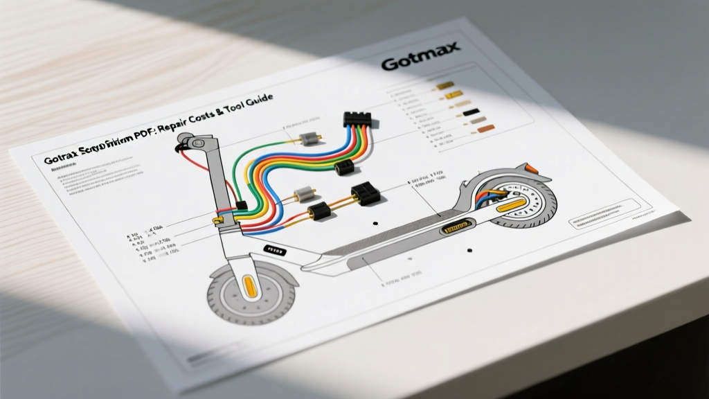
The Reality of Sourcing a Gotrax Scooter Wiring Diagram PDF
When an electric scooter suffers an electrical failure, the immediate instinct for any DIY mechanic is to search for a factory service manual. However, finding an official, comprehensive Gotrax scooter wiring diagram PDF is notoriously difficult. Like many direct-to-consumer micro-mobility brands, Gotrax tightly guards its proprietary schematics to discourage unauthorized repairs that could compromise lithium-ion battery safety or void the manufacturer warranty. The diagrams circulating on forums and repair communities are typically reverse-engineered by enthusiasts mapping out the G3, G4, or Apex series controllers.
Despite the lack of official factory PDFs, the fundamental architecture of e-scooter electrical systems remains highly standardized. By understanding the universal wire color codes, AWG ratings, and connector pinouts used in 36V and 48V scooter platforms, you can effectively diagnose and repair your vehicle. This guide shifts the focus from simply reading a diagram to executing a rigorous Cost & Tool Requirements Analysis for Gotrax scooter electrical repairs. We will break down the exact diagnostic toolkit, material costs, and step-by-step testing procedures required to fix common controller, throttle, and motor hall sensor failures.
Essential Diagnostic Tooling & Investment Costs
Before attempting to trace a short circuit or a failed hall sensor using a community-sourced wiring diagram, you must assemble a proper diagnostic toolkit. E-scooters operate in high-vibration, moisture-prone environments, meaning standard automotive crimpers and cheap soldering irons will result in rapid secondary failures. Below is the required tooling for professional-grade e-scooter electrical repair.
Multimeter & Oscilloscope Requirements
A standard digital multimeter (DMM) is mandatory for checking continuity, battery voltage, and throttle signal output. For accurate diagnostics on a Gotrax 36V system, your DMM must be rated for at least CAT II 600V to safely handle potential voltage spikes from the brushless DC (BLDC) motor's regenerative braking. Entry-level multimeters like the AstroAI DM6000R cost around $35, but professionals prefer the Fluke 115 ($170) for its true-RMS accuracy when measuring the pulse-width modulation (PWM) signals from the controller to the motor phases.
Soldering & Wire Prep Stations
E-scooter battery packs and controllers rely heavily on silicone-insulated wires that require high-heat soldering. A standard 40W pencil iron is insufficient for 12 AWG battery discharge leads due to thermal dissipation. You need a temperature-controlled soldering station (e.g., Hakko FX-888D, ~$110) capable of sustaining 750°F (400°C) to properly flow 60/40 rosin-core solder onto thick copper strands without melting the adjacent Higo connector housings. Additionally, a precision wire stripper like the Knipex MultiStrip 10 (~$85) is required to strip 22 AWG signal wires without nicking the copper core, which is a primary cause of internal wire fatigue and intermittent throttle failure.
Wire Gauge, Connector Specs, and Material Costs
When utilizing a reverse-engineered Gotrax wiring diagram to replace damaged harnesses, matching the original equipment manufacturer (OEM) specifications is critical for safety and performance. Undersized wires will cause voltage sag, triggering the Battery Management System (BMS) low-voltage cutoff, while oversized wires add unnecessary weight and resist proper routing through the steering stem.
| Circuit Application | AWG Size | Wire Type | Connector Type | Est. Material Cost |
|---|---|---|---|---|
| Battery to Controller (Main Discharge) | 12 AWG | Silicone Stranded | XT60 / XT90 | $14 (per meter) |
| Controller to Motor (Phase Wires) | 14 AWG | Silicone Stranded | Bullet (4mm) / Higo | $11 (per meter) |
| Motor Hall Sensors | 22 AWG | PVC / Silicone | Higo Mini-A (5-Pin) | $8 (connector kit) |
| Throttle / Brake Levers / Display | 24 AWG | PVC Stranded | JST-SM (3-Pin / 4-Pin) | $6 (connector kit) |
| BMS Balance Leads | 18 AWG | High-Temp Teflon | JST-XH | $9 (harness kit) |
According to the SAE J1128 standard for low-tension primary cables, wire gauge selection must account for both current draw and ambient temperature. Because Gotrax scooter controllers are often sealed in enclosed aluminum decks with minimal airflow, ambient temperatures can easily exceed 50°C (122°F) during sustained hill climbs. Therefore, always use high-strand-count silicone wire (e.g., 12 AWG with 680 strands of 0.08mm copper) rather than standard automotive PVC wire, as silicone maintains flexibility and prevents insulation melting near the controller's MOSFETs.
Step-by-Step Diagnostic Cost Analysis: Throttle & Hall Sensors
The most common failures mapped on any Gotrax scooter wiring diagram PDF involve the throttle assembly and the motor hall sensors. Replacing these components blindly at a local scooter repair shop typically costs between $80 and $150 in labor and markup. By performing the diagnostics yourself, the hard cost drops to under $25 in parts.
Throttle Signal Testing
The Gotrax throttle utilizes a standard 3-wire Hall-effect sensor configuration. Based on standard e-scooter schematics, the pinout is as follows:
- Pin 1 (Red): 5V VCC (Supplied by the controller's internal voltage regulator)
- Pin 2 (Black): Ground (GND)
- Pin 3 (White/Green): Signal Output (0.8V at rest, 3.6V at full depression)
Diagnostic Procedure: Disconnect the throttle from the controller. Set your multimeter to DC Voltage. Back-probe the controller-side connector. Turn the scooter on. You should read exactly 5.0V between the Red and Black pins. If you read 0V, the controller's internal 5V regulator has failed, requiring a full controller replacement ($65-$120). If 5V is present, reconnect the throttle, back-probe the Signal wire, and twist the grip. If the voltage does not smoothly sweep from ~0.8V to ~3.6V, the throttle magnet has slipped, and a replacement throttle assembly ($18) is required.
Motor Hall Sensor Pinout & Failure Modes
Brushless hub motors rely on three internal hall sensors to tell the controller the exact position of the rotor magnets. The wiring harness uses a 5-pin waterproof Higo (Julet) connector. The standard color code is:
- Red: 5V VCC
- Black: Ground
- Yellow, Green, Blue: Phase A, B, and C signals
If your Gotrax scooter stutters, makes a loud grinding noise, or throws an Error Code 02 or 07, a hall sensor has likely failed due to water ingress or heat degradation. Testing requires checking the continuity of the 22 AWG wires from the motor axle exit to the controller plug. A single broken strand inside the waterproof heat-shrink tubing will cause the controller to lose rotor synchronization. Repairing this requires cutting the damaged Higo connector, stripping the 22 AWG wires, and soldering a new Higo pigtail ($8). Attempting to use standard solder sleeves without marine-grade adhesive-lined heat shrink will result in immediate corrosion failure.
BMS Wiring and Battery Pack Safety Thresholds
When consulting a wiring diagram that extends into the battery enclosure, you are dealing with the Battery Management System (BMS). Gotrax typically uses 10S (36V) or 13S (48V) lithium-ion cell configurations. The BMS relies on a ribbon cable of 18 AWG balance wires connected to the cell groups via JST-XH connectors.
As noted in technical resources like Battery University's BMS guidelines, the balance leads must be connected in strict sequential order from B0 (main negative) to B10/B13 (main positive). If a balance wire is severed during a deck modification or repair, the BMS will permanently lock out the pack to prevent cell overcharging and thermal runaway.
Cost Warning: If your multimeter reads a voltage differential of greater than 0.15V between adjacent balance pins on the BMS connector, the cell groups are severely unbalanced or degraded. No amount of wiring repair will fix this. At this threshold, the DIY cost analysis shifts from a $20 wiring repair to a $250+ complete battery pack replacement. Always consult the Gotrax Official Support documentation regarding battery safety warnings before attempting to bypass a locked BMS, as doing so poses a severe fire hazard.
Summary: When to Abandon DIY Repairs
Utilizing a Gotrax scooter wiring diagram PDF to execute your own repairs is highly cost-effective for peripheral components like throttles, brake light switches, and display harnesses. The initial tooling investment of roughly $150 pays for itself after a single successful controller or motor hall sensor repair. However, if your diagnostic multimeter testing reveals internal BMS faults, severed 12 AWG battery discharge leads inside the steering column, or blown controller MOSFETs, the required tooling (spot welders, high-current oscilloscopes) and safety liabilities exceed the scope of standard DIY analysis. In those cases, the most economically sound decision is to source an OEM replacement harness or controller assembly rather than attempting to splice high-current lithium-ion circuits.