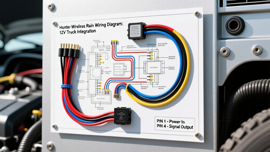
Adapting Irrigation Tech for Expedition Vehicles
When building expedition trucks, overland RVs, or custom agricultural transport rigs, automating exterior components based on weather conditions is a critical upgrade. While automotive OEMs use localized windshield rain sensors (like Gentex or Hella modules) strictly for wiper control, they do not offer wide-area RF precipitation detection. This is where the hunter wireless rain sensor wiring diagram becomes a highly searched, albeit unconventional, resource for advanced vehicle electricians. By integrating the Hunter Rain-Clik wireless receiver into a 12VDC automotive harness, builders can trigger automated awning retractions, shut off exterior 12V water pumps, or deploy weather-sealing actuators when rain is detected within a 300-foot RF radius.
However, integrating this sensor into a vehicle is not a simple plug-and-play task. The Hunter receiver is engineered for 24VAC residential irrigation systems, whereas your truck or RV operates on a 12VDC negative-ground architecture. Directly splicing these systems will result in catastrophic failure of your vehicle's body control module (BCM) or a melted harness. This complete wiring walkthrough details the exact isolation relays, step-up inverters, and SAE-compliant wire gauges required to safely bridge this gap.
The Core Challenge: 24VAC vs. 12VDC Architecture
The Hunter Wireless Rain-Clik receiver utilizes an internal electromechanical relay designed to interrupt a 24VAC common wire circuit. In a vehicle, we must use this switching action to trigger a 12VDC automotive relay without allowing the 24VAC current to backfeed into the vehicle's DC ground plane. To achieve this, we employ an optocoupler isolation module or a dedicated 12VDC-to-24VAC inverter paired with a solid-state relay (SSR). According to the official Hunter Industries Rain-Clik documentation, the sensor's hygroscopic disc expands to open the circuit, meaning our automotive harness must be designed to trigger on an open-circuit signal (fail-safe logic) or utilize a normally-closed relay configuration.
Required Components and SAE Wire Specifications
According to SAE J1128 standards for low-tension primary automotive cables, selecting the correct wire gauge and insulation type is vital to prevent voltage drop and thermal runaway in engine bay or undercarriage routing.
| Circuit Function | Wire Color | AWG Size | Strand Count | Max Current |
|---|---|---|---|---|
| Main 12V+ Feed (Ignition) | Red | 14 AWG | 41/30 | 15A |
| Vehicle Chassis Ground | Black | 14 AWG | 41/30 | 15A |
| Isolation Relay Trigger | Yellow | 18 AWG | 16/30 | 3A |
| Switched 12V+ Load (Awning/Pump) | Blue | 12 AWG | 65/30 | 20A |
| 24VAC Inverter Feed | Orange | 16 AWG | 26/30 | 5A |
Complete Wiring Diagram Walkthrough
Below is the step-by-step schematic logic for routing the Hunter wireless rain sensor wiring diagram into a standard 5-pin Bosch-style automotive relay harness, utilizing an isolation barrier.
Step 1: Powering the Receiver via Inverter
The Hunter receiver requires 24VAC. You must install a 12VDC to 24VAC step-up transformer (commonly used in RV thermostat upgrades or marine instrument lighting). Tap a switched 12V+ ignition source using a 5A ATC fuse. Connect the 16 AWG Orange wire from the fuse to the inverter's DC+ terminal, and the Black ground to the vehicle chassis. The inverter will output 24VAC to the Hunter receiver's transformer terminals.
Step 2: The Optocoupler Isolation Barrier
Never wire the Hunter receiver's 'Sensor' and 'Common' terminals directly to a 12VDC relay coil. Instead, wire the Hunter's internal switch in series with the 24VAC output and the input side of a 24VAC-rated optocoupler module. When the rain sensor's hygroscopic disc expands and opens the circuit, the optocoupler's internal LED turns off, breaking the signal to the DC side without any physical electrical connection between the AC and DC planes.
Step 3: Wiring the 12VDC Automotive Relay (Bosch 5-Pin)
The output side of the optocoupler will act as the ground switch for your main 12VDC automotive relay. Referencing the Littelfuse Automotive Relay Guide, we configure the standard ISO mini relay as follows:
- Pin 86 (Coil +): Connect to a constant 12V+ source via a 3A inline fuse (18 AWG Red).
- Pin 85 (Coil -): Connect to the switched ground output of the optocoupler (18 AWG Yellow).
- Pin 30 (Common): Connect to the main battery positive via a 20A Maxi fuse (12 AWG Red).
- Pin 87 (Normally Open): Connect to the 12V+ trigger wire of your exterior load (e.g., awning retract motor or water pump solenoid) using 12 AWG Blue wire.
- Pin 87a (Normally Closed): Leave unsealed and insulated with heat shrink; not used in this rain-trigger configuration.
CAN-Bus Integration for Modern Overland Trucks
On modern expedition vehicles (e.g., 2020+ Ford Transit, Mercedes Sprinter, or RAM ProMaster), tapping directly into the battery for exterior loads is often prohibited by the Body Control Module (BCM) smart-shunt logic. If the BCM detects an unauthorized parasitic draw or a relay coil pulling current directly from the battery post, it may trigger a 'Battery Saver Mode' and cut power to the auxiliary bus.
To integrate the Hunter sensor's 12VDC relay output into a CAN-bus controlled environment, you must use a CAN-bus decoder module or interface with an upfitter auxiliary switch bank. Connect the output of Pin 87 not directly to the awning motor, but to the signal input of the vehicle's OEM upfitter interface module. This ensures the rain sensor's trigger request is processed as a validated logic gate signal rather than a raw current draw, keeping the vehicle's warranty intact and preventing BCM fault codes.
Real-World Troubleshooting: RF Interference and Voltage Drop
Integrating RF sensors into expedition vehicles introduces unique failure modes not found in residential installations. The steel or aluminum bed of a truck acts as a Faraday cage, severely limiting the 433 MHz RF signal from the Hunter transmitter.
Symptom-Cause-Fix Decision Tree
- Symptom: Sensor fails to trigger relay when wet.
- Cause A: Receiver mounted inside the truck cab or below a metal tonneau cover.
- Fix: Relocate the receiver to the roof rack or use an external 433 MHz RF antenna extension kit routed through a weatherproof grommet into the cabin.
- Cause B: Voltage drop across the 12VDC-to-24VAC inverter under heavy alternator ripple.
- Fix: Install a 4700µF electrolytic capacitor across the DC input terminals of the inverter to smooth out alternator AC ripple, which can cause the Hunter receiver's internal logic board to reset or fail to register the hygroscopic switch state.
- Symptom: Relay chatters rapidly during light mist.
- Cause: Inductive kickback from the awning motor coil backfeeding into the optocoupler.
- Fix: Solder a 1N4007 flyback diode across Pins 85 and 86 of the automotive relay (stripe facing Pin 86) to absorb the voltage spike, as recommended for inductive loads in mobile environments.
Weatherproofing and SAE Compliance
Because the Hunter receiver is designed for outdoor residential use, its enclosure is UV and water-resistant, but the wire entry points are not rated for the high-pressure spray and road debris encountered on a vehicle undercarriage or exterior rack. All splice points must be sealed using dual-wall adhesive-lined heat shrink tubing compliant with SAE J1928 environmental testing standards. Furthermore, any harness routed through the vehicle firewall or truck bed floor must utilize a rubber grommet and a loop of dielectric grease to prevent capillary action from wicking moisture into the relay sockets.
By meticulously following this hunter wireless rain sensor wiring diagram adaptation, you ensure that your vehicle's exterior automation systems respond reliably to precipitation, protecting expensive awnings and preventing water pump dry-runs, all while maintaining strict isolation between the AC sensor circuit and the vehicle's sensitive DC CAN-bus architecture.