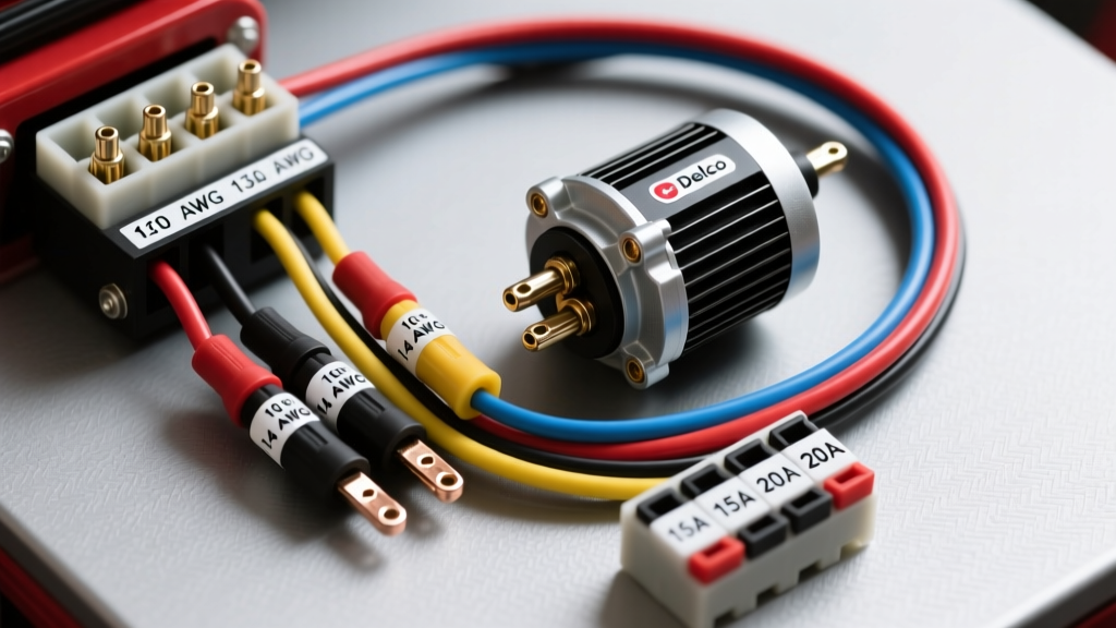
The Massey Ferguson 135 Electrical Baseline
The Massey Ferguson 135 (MF135) remains one of the most reliable utility tractors ever produced, but its original 12-volt electrical architecture was designed for the minimal loads of the 1960s and 1970s. Factory configurations typically relied on a Lucas C40 dynamo (generator) paired with an RB106 mechanical voltage regulator and a moving-iron ammeter. While adequate for basic ignition and a single headlight circuit, this system fails under the demands of modern LED work lights, 12V water pumps, or GPS guidance systems. Furthermore, the Lucas dynamo produces negligible amperage at low RPMs, leading to chronic battery depletion during loader work or PTO-driven applications.
This modification guide details the complete removal of the Lucas charging system and the installation of a modern, internally regulated Delco 10SI alternator, alongside the integration of a centralized ATC fuse block. By referencing this Massey Ferguson wiring diagram 135 upgrade path, you will transform the tractor into a reliable, high-output platform capable of supporting modern agricultural accessories.
Core Upgrade: Lucas Dynamo to Delco 10SI Alternator Conversion
The Delco 10SI alternator (typically rated at 63A or 94A) is the industry standard for tractor charging upgrades due to its internal regulation, robust diode trio, and wide availability. Unlike the Lucas C40, which requires a complex multi-wire harness routed to the dashboard-mounted RB106 control box, the 10SI requires only three connections to function flawlessly.
Before beginning the wiring phase, the original RB106 voltage regulator must be completely bypassed or removed. The heavy-gauge wires that previously ran from the dynamo to the regulator and back to the ammeter must be discarded. Retaining the original ammeter in series with a 94-amp alternator is a severe fire hazard; the factory 10 AWG ammeter shunt wiring will melt under high-load charging conditions. The recommended protocol is to delete the ammeter entirely and install a digital or analog voltmeter wired to a switched 12V source.
Alternator Pinout & Excitation Circuit
The Delco 10SI utilizes a standardized 2-pin connector. Terminal 1 is the excitation/field trigger, and Terminal 2 is the voltage sense circuit. Proper routing of these circuits is critical to prevent parasitic battery drain and alternator backfeeding.
| Terminal | Function | Wire Color | AWG Size | Routing Destination |
|---|---|---|---|---|
| BAT (Stud) | Main Output | Red | 8 AWG (GXL) | Starter Solenoid Battery Post (via 100A Mega Fuse) |
| Pin 1 | Excitation / Field | Yellow | 14 AWG (TXL) | Ignition Switch "Run" Terminal (via 10-ohm resistor or dash light) |
| Pin 2 | Voltage Sense | Red | 14 AWG (TXL) | Jumped to BAT Stud or Battery Positive |
Crucial E-E-A-T Note on Terminal 1: If your MF135 dashboard lacks an alternator warning light (idiot light), you must install a 10-ohm, 2-watt resistor in-line with the Terminal 1 excitation wire, or wire a 194 bulb in parallel. The internal voltage regulator requires a slight initial resistance to initialize the field coils. Without this resistor or bulb, the alternator may fail to "excite" and begin charging until the engine is revved significantly, or it may backfeed 12V into the ignition coil when the key is turned off, causing the tractor to diesel (run-on).
Modernizing the Harness: Adding a Fused Distribution Block
The original MF135 wiring harness routes all accessory power directly through the ignition switch or relies on inline glass fuses that corrode rapidly in agricultural environments. To support modern modifications, mount a Bussmann or Littelfuse 6-circuit ATC fuse block in a protected location under the dashboard or inside a sealed battery box.
Power for the fuse block must be sourced directly from the starter solenoid battery terminal or the alternator BAT terminal, protected by a 30-amp or 40-amp maxi-fuse. This ensures that high-draw accessories like LED light bars or hydraulic solenoid valves do not route their return current through the aging factory ignition switch.
Circuit Routing & AWG Sizing Chart
When building the new accessory harness, adhere strictly to SAE J1128 standards for low-tension primary cables. Use Cross-Linked Polyethylene (GXL or TXL) wire, which offers superior resistance to heat, diesel fuel, and abrasion compared to standard PVC wire.
| Circuit Function | Fuse Rating | Wire Gauge | Connector Type |
|---|---|---|---|
| LED Work Lights (Rear) | 15A ATC | 14 AWG | Weather-Pack 2-Pin |
| LED Work Lights (Front) | 15A ATC | 14 AWG | Weather-Pack 2-Pin |
| Cab Accessories / GPS | 10A ATC | 16 AWG | Deutsch DT 4-Pin |
| 12V Auxiliary Receptacle | 20A ATC | 12 AWG | Heavy-Duty Ring Terminal |
| Voltmeter / Dash Illumination | 5A ATC | 18 AWG | Insulated Spade |
Step-by-Step Wiring Execution
- Disconnect and Isolate: Remove the negative battery cable. Unbolt the Lucas C40 dynamo and the RB106 regulator. Cut and cap the original harness wires leading to the regulator to prevent future short circuits.
- Mount the Alternator: Fabricate or purchase an MF135 to Delco alternator mounting bracket. Ensure the alternator case is making bare-metal contact with the engine block. If painting or powder coating the bracket, use a grounding strap (minimum 6 AWG) from the alternator casing to the engine block.
- Terminate the Main Output: Crimp a 3/8-inch heavy-duty ring terminal onto the 8 AWG red GXL wire using a ratcheting crimper. Seal the termination with adhesive-lined dual-wall heat shrink. Route this wire to the starter solenoid battery post, installing a 100A ANL or Mega fuse within 12 inches of the solenoid.
- Wire the Excitation Circuit: Run the 14 AWG yellow wire from the alternator Pin 1 through the firewall to the ignition switch. Tap into the switched 12V "Run" terminal. Solder the 10-ohm resistor inline and seal with heat shrink.
- Establish Voltage Sense: Crimp a ring terminal to the 14 AWG red sense wire and secure it directly to the alternator BAT stud alongside the main output wire. This forces the internal regulator to read voltage exactly at the point of generation, compensating for any voltage drop in the main harness.
- Grounding Protocol: Agricultural tractors suffer from poor ground continuity due to rust and grease. Install a dedicated 4 AWG ground strap from the engine block to the chassis, and another from the chassis to the battery negative terminal. Sand all contact points down to bare, shiny metal before torquing the bolts.
Troubleshooting the Modification
Even with a flawless schematic, real-world agricultural environments introduce variables that can cause electrical faults. Consult this decision tree if your upgraded MF135 exhibits anomalies:
- Symptom: Battery drains overnight.
- Cause: Alternator backfeeding through the excitation circuit due to a missing resistor or a shorted dash diode.
- Fix: Disconnect the 2-pin plug. If the drain stops, test the ignition switch for continuity in the "Off" position. Ensure the 10-ohm resistor is properly installed and not bypassed.
- Symptom: Alternator whines and lights flicker at low RPM.
- Cause: High resistance on the voltage sense wire (Terminal 2) or a slipping drive belt.
- Fix: Verify Terminal 2 is jumped directly to the BAT stud. Check belt tension; the 10SI requires significantly more belt wrap and tension than the Lucas dynamo to prevent slip under high-amp loads.
- Symptom: Voltmeter reads 15.5V+ and battery boils.
- Cause: Internal regulator failure or poor alternator case grounding.
- Fix: The regulator relies on the alternator case for its ground reference. If the mounting brackets are painted or corroded, the regulator cannot read system voltage and will max out the field circuit. Clean mounting surfaces and reinstall.
Authoritative References
For further validation of wire ampacity and heavy-duty alternator specifications, consult the following industry standards and technical documentation:
- SAE J1128: Low Tension Primary Cable Standard - Defines the thermal and abrasion requirements for GXL/TXL automotive and agricultural wire.
- Delco Remy Alternator Technical Service Manuals - Provides OEM pinout diagrams and excitation resistance parameters for the 10SI and 12SI series.