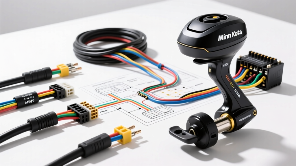
Introduction to Marine DC Electrical Integration
Integrating a high-thrust electric propulsion system into a marine vehicle or custom truck-bed camper requires strict adherence to DC electrical standards. Whether you are rigging a fiberglass bass boat, an aluminum jon boat, or a specialized overland rig, referencing the correct Minn Kota trolling motor wiring diagram is critical to prevent voltage drop, thermal runaway, and galvanic corrosion. This guide provides a comprehensive cost and tool requirements analysis for building a reliable 24V or 36V marine battery bank and motor circuit, ensuring your installation meets both manufacturer specifications and marine safety codes.
Decoding the Minn Kota Wiring Schematic: 24V Series Configuration
Most modern 80lb to 112lb thrust trolling motors operate on a 24V or 36V system. The most common configuration is the 24V series circuit, which utilizes two 12V deep-cycle or lithium marine batteries. Understanding the schematic is the first step in calculating your material costs.
24V Series Wiring Pinout & Routing
- Battery 1 (12V): The positive terminal routes through a 60A or 80A inline resettable circuit breaker, then to the Positive Pin on the bow-mounted quick-release receptacle.
- Series Jumper: A heavy-gauge jumper wire connects the Negative terminal of Battery 1 to the Positive terminal of Battery 2. This jumper must be the same AWG as the main run to prevent a bottleneck.
- Battery 2 (12V): The negative terminal routes directly to the Negative Pin on the quick-release receptacle.
For systems utilizing a 12/24V alternator charging setup, a 3-wire or 4-wire plug (such as the Minn Kota MKR-26) is required. In a 3-wire MKR-26 plug, Pin 1 is 24V+ (Red), Pin 2 is 12V+ (Orange), and Pin 3 is the Common Ground (Black). Always verify your specific Minn Kota owner's manual before terminating multi-pin connectors, as miswiring the 12V tap can instantly fry the motor's control board.
Mandatory Tool Requirements for High-Amperage DC Wiring
Working with 2 AWG to 6 AWG marine wire requires specialized tooling. Standard automotive crimpers will fail to achieve the necessary compression ratio, leading to high-resistance connections that melt under the sustained 40A+ draw of a trolling motor.
Essential Tool Checklist
| Tool | Specification | Purpose |
|---|---|---|
| Hydraulic or Ratcheting Crimper | 8 AWG to 2/0 AWG capacity | Ensures uniform, gas-tight compression on heavy ring terminals. |
| Marine Wire Stripper | Self-adjusting, 8-2 AWG | Prevents nicking the fine-strand tinned copper conductors. |
| Industrial Heat Gun | Dual-temp (up to 500°F) | Required for activating 3:1 adhesive-lined marine heat shrink. |
| Digital Multimeter | True RMS, 1000V CAT III | For voltage drop testing and verifying series battery bank output. |
| Torque Wrench | 1/4-inch drive, 5-25 ft-lbs | Crucial for battery terminal studs to prevent arcing and loosening. |
According to the American Boat & Yacht Council (ABYC) E-11 standard, solder-only connections are strictly prohibited in marine environments due to vibration-induced fatigue cracking. Every termination must be a mechanical crimp, optionally followed by solder, and sealed with adhesive heat shrink.
Material Cost Analysis: Building a Premium 24V System
Budgeting for a trolling motor wiring harness requires factoring in marine-grade materials. Standard automotive copper wire (SAE J1128) is not tinned and will rapidly corrode in marine or high-humidity truck-bed environments. You must purchase UL 1426 certified marine-grade tinned copper wire. Below is a cost breakdown for a high-quality 15-foot run (30 feet total wire) using 4 AWG wire, suitable for motors up to 112 lbs of thrust (approx. 50A max draw).
Bill of Materials (BOM) & Estimated Costs
| Component | Specification | Quantity | Est. Cost (USD) |
|---|---|---|---|
| Marine Wire (Red/Black) | 4 AWG UL 1426 Tinned Copper | 30 ft | $115.00 |
| Series Jumper Wire | 4 AWG Custom Length (2 ft) | 1 | $8.00 |
| Inline Circuit Breaker | 60A Resettable (Marinco/Bussmann) | 1 | $28.00 |
| Quick-Release Plug/Receptacle | 2-Wire 50A/60A (e.g., MKR-26) | 1 set | $45.00 |
| Ring Terminals | 4 AWG to 3/8' Stud, Tinned | 6 | $12.00 |
| Adhesive Heat Shrink | 3:1 Ratio, 3/8' diameter | 10 pcs | $15.00 |
| Cable Clamps & Loom | UV-resistant split loom, SS clamps | Kit | $22.00 |
| Total Estimated Cost | $245.00 |
Note: Prices fluctuate based on copper market rates. Sourcing wire from dedicated marine electrical suppliers like Ancor ensures genuine tinned stranding, whereas discount marketplaces often sell copper-clad aluminum (CCA) wire disguised as marine wire, which poses a severe fire risk.
Installation Rules & Torque Specifications
When executing the Minn Kota wiring diagram, physical placement of components is just as important as the electrical routing. ABYC standards dictate that the primary overcurrent protection (the circuit breaker) must be installed within 7 inches of the positive battery terminal. If the wire runs through a conduit or loom before reaching the breaker, the entire un-fused length must be protected against chafing.
Torque Specs for DC Terminals
Under-torqued battery terminals create micro-arcing, which increases resistance and generates immense heat. Over-torquing can strip the soft lead threads of marine battery posts or snap copper studs on the motor receptacle.
- Standard 3/8' Battery Stud: 12 to 15 ft-lbs.
- 5/16' Battery Stud: 8 to 10 ft-lbs.
- Minn Kota Motor Receptacle Lugs: Consult manufacturer spec, typically 4 to 6 ft-lbs (use caution to avoid cracking the plastic housing).
Voltage Drop Calculations & Troubleshooting
The most common failure mode in aftermarket trolling motor installations is excessive voltage drop, which causes the motor to lose thrust, shut down prematurely, or trigger the internal low-voltage alarm. Minn Kota recommends keeping the total voltage drop below 10% of the system voltage at maximum amperage draw.
Decision Tree: Motor Intermittently Cuts Out Under Load
- Step 1: Check Battery Bank Voltage. Use a multimeter at the battery terminals while the motor is running at speed 10. If a 24V system drops below 22.0V, the batteries are undersized, sulfated, or depleted.
- Step 2: Test the Series Jumper. Measure voltage across the jumper wire connecting Battery 1 Negative to Battery 2 Positive. A reading above 0.1V indicates a poor crimp or an undersized jumper wire.
- Step 3: Inspect the Quick-Release Plug. Disconnect the bow plug and inspect the male/female pins. Look for black carbon scoring or melted plastic. High-amperage draws will melt standard 50A plugs if the pins lose tension over time. Upgrade to a heavy-duty 60A or 100A rated marine connector if scorching is present.
- Step 4: Verify Ground Integrity. Ensure the negative wire routing back to the battery bank is free of corrosion. Unlike automotive chassis grounding, marine DC systems must utilize dedicated, insulated negative return wires routed directly back to the battery bus or negative terminal.
Summary
Successfully wiring a high-thrust trolling motor requires moving beyond basic automotive wiring practices. By investing in proper ratcheting crimpers, UL 1426 tinned copper wire, and adhering to ABYC circuit breaker placement rules, you ensure your marine vehicle's electrical system operates safely and efficiently. While the upfront material cost for a premium 4 AWG 24V harness may approach $250, this investment prevents catastrophic thermal events and ensures your Minn Kota motor delivers maximum thrust on the water.