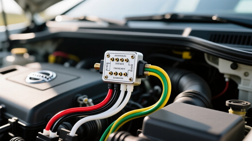
Understanding the Nissan 5-Wire MAF Sensor Architecture
For beginners stepping into automotive electrical diagnostics, the Mass Air Flow (MAF) sensor is one of the most critical components to understand. In many modern Nissan and Infiniti vehicles equipped with VQ, QR, and VK series engines, the engine control module (ECM) relies on a combined MAF and Intake Air Temperature (IAT) sensor. This integration results in a 5-pin connector rather than the traditional 3-pin or 4-pin setups found on older vehicles.
When searching for a Nissan 5 wire MAF sensor wiring diagram, it is essential to recognize that you are dealing with two distinct circuits housed in a single Hitachi-manufactured sensor body. The MAF portion utilizes a hot-wire anemometer to measure air density and volume, while the IAT portion uses a negative temperature coefficient (NTC) thermistor to measure the thermal density of the incoming air. Understanding how these five wires interact with the ECM is the first step toward accurate diagnostics and repair.
Anatomy of the 5-Pin Sumitomo Connector
Nissan typically uses a sealed 5-pin Sumitomo or Yazaki weather-pack connector for this sensor. The connector features a silicone radial seal to prevent moisture ingress, which is critical given the sensor's location on the cold air intake tube or airbox. Over time, engine bay heat cycling and vibration can cause wire chafing or terminal oxidation. Before replacing a perfectly good sensor, a beginner must learn to verify the wiring harness.
Pinout Configuration and Wire Color Chart
The following table outlines the standard pinout for a typical Nissan 5-wire MAF/IAT combo sensor (commonly found on models like the Altima, Sentra, and 350Z). Always verify against the specific Nissan Factory Service Manuals (FSM) for your exact model year, as ECM terminal numbers vary by chassis.
| Pin | Function | Typical Wire Color | Wire Gauge (AWG) | Destination |
|---|---|---|---|---|
| 1 | IAT Signal Output | Orange or White | 22 AWG | ECM (Analog Input) |
| 2 | MAF Signal Output | Light Green or Blue | 22 AWG | ECM (Analog Input) |
| 3 | Sensor Ground | Black or Brown | 20 AWG | ECM Ground Driver |
| 4 | 12V Power Supply | Yellow or Red | 18 AWG | IPDM / ECM Relay |
| 5 | IAT Ground / Shield | Black w/ Stripe | 22 AWG | ECM Shield Ground |
Note: Wire colors may feature a secondary tracer stripe depending on the exact harness batch and manufacturing plant.
Step-by-Step Wiring Verification for Beginners
Diagnostic trouble codes (DTCs) like P0100 (MAF Circuit Malfunction) or P0110 (IAT Circuit Malfunction) do not automatically mean the sensor is dead. In fact, a significant percentage of these codes stem from wiring faults. Here is how to test the circuit using a Digital Multimeter (DMM).
1. Verifying Power and Ground Integrity
Set your DMM to DC Volts. Backprobe Pin 4 (Power) and Pin 3 (Ground) at the sensor connector with the ignition in the 'ON' position (engine off). You should read between 11.5V and 12.5V. If you read 0V, check the Intelligent Power Distribution Module (IPDM) in the engine bay for a blown MAF relay or fuse. If you read battery voltage but the sensor fails to operate, perform a voltage drop test on the ground circuit (Pin 3). A voltage drop greater than 0.1V on the ground side indicates high resistance, usually caused by a corroded ECM ground splice or a loose terminal.
2. Testing the Signal Circuits
The MAF signal (Pin 2) operates on a 0-5V analog scale. At key-on, engine-off (KOEO), you should see a baseline voltage of roughly 0.8V to 1.0V. When the engine is idling, this voltage typically stabilizes between 1.2V and 1.8V depending on engine displacement and cam timing. As you rev the engine, the voltage should climb smoothly toward 4.0V - 4.5V. Any sudden dropouts to 0V or spikes to 5V on the DMM indicate a break or short in the Light Green/Blue signal wire.
The IAT signal (Pin 1) is a 5V reference signal that drops in voltage as temperature rises. At ambient room temperature (approx. 68°F / 20°C), expect to see roughly 2.5V to 3.0V. Pin 5 acts as the dedicated low-reference ground for the thermistor circuit, isolating it from the noisy MAF ground.
Common Wiring Failures in Nissan Applications
When working with Nissan engine harnesses, beginners should look out for three highly specific failure modes:
- Airbox Chafing: The harness routing near the factory airbox often rubs against the plastic molding or the metal hose clamp securing the intake tube. This wears through the 22 AWG wire insulation, causing the MAF signal to short to ground and triggering a P0102 (MAF Circuit Low Input).
- Terminal Spread: The female terminals inside the Sumitomo connector can spread open over time due to repeated sensor removals for cleaning or replacement. This causes intermittent connection loss over bumps. Use a terminal pick to gently squeeze the female tabs back into a 'U' shape.
- Aftermarket Intake Interference: Cold air intakes often route the sensor closer to the radiator fans or alternator, exposing the unshielded signal wires to Electromagnetic Interference (EMI). This causes erratic fuel trims without throwing a hard DTC.
Best Practices for Sensor Wire Repair
If you identify a broken or corroded wire, do not simply twist the wires together and wrap them in electrical tape. Automotive sensor circuits require strict adherence to resistance and shielding standards. According to the SAE J1128 Low Tension Primary Cable Standard, sensor wires must maintain specific thermal and abrasion resistance ratings.
When repairing a 22 AWG MAF signal wire, always use matching AWG cross-linked polyethylene (XLPE) wire. Solder the connection using rosin-core solder to prevent oxidation, and seal the repair using dual-wall, adhesive-lined marine heat shrink. This ensures a waterproof seal that prevents capillary action from drawing moisture into the ECM connector. For detailed component specifications and OEM replacement guidelines, technicians frequently reference Hitachi Astemo Engine Management Systems documentation, as Hitachi is the primary OE supplier for Nissan airflow sensors.
By mastering the fundamentals of this 5-wire diagram, you transition from simply swapping expensive sensors to accurately diagnosing the root electrical cause, saving time and ensuring long-term vehicle reliability.