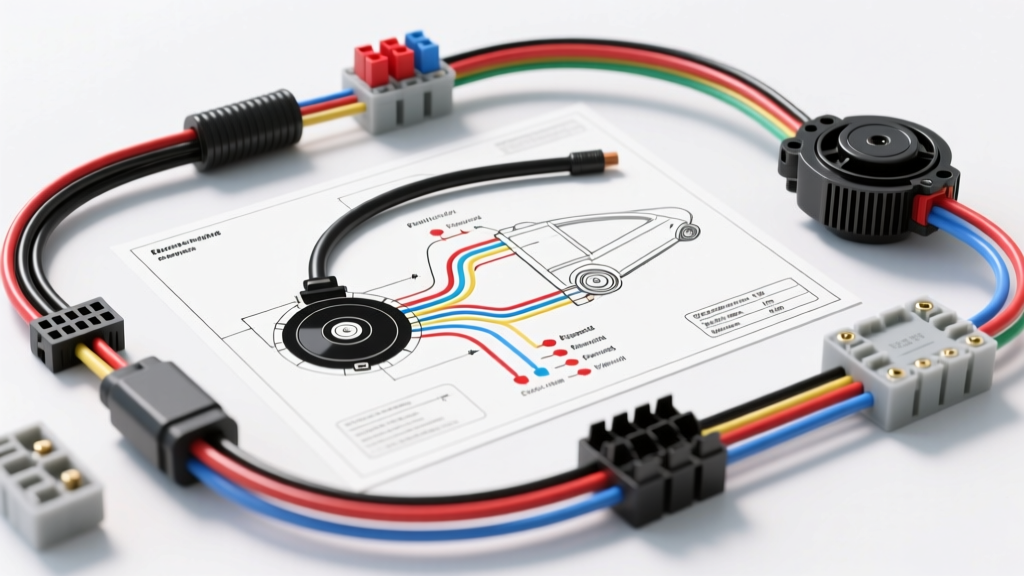
Introduction to Wiper Circuit Fundamentals
For many automotive DIYers and beginning technicians, windshield wiper circuits seem unnecessarily complicated. Unlike a simple headlight circuit that merely routes power to a bulb, a wiper system must manage multiple speeds, integrate a washer pump, and feature a mechanism that ensures the blades return to the bottom of the windshield before shutting off. When you first look at a car wiper wiring diagram, the web of relays, switches, and internal motor contacts can be overwhelming. However, once you understand the core physics of the multi-speed motor and the logic of the internal park switch, these schematics become incredibly logical. This beginner-friendly guide will break down the fundamental components, wire color codes, and circuit paths found in classic and modern multi-speed wiper systems.
Decoding Diagram Symbols and Core Components
Before tracing power, you must identify the primary actors in the schematic. A standard direct-wire wiper system (common in GM, older Ford, and Chrysler vehicles) relies on four main components:
- The Multi-Function Switch: The dashboard or steering column stalk that the driver interacts with. It routes battery voltage to different circuits based on the selected mode (Off, Low, High, Mist, Washer).
- The Wiper Motor Assembly: Contains both the electric motor and the gearbox. Crucially, it houses the internal cam-operated park switch.
- The Washer Pump: A small, reversible or single-direction 12V DC motor that sprays the fluid.
- The Fuse/Breaker Panel: Wiper motors draw significant amperage, especially when pushing against heavy snow or dry glass. They are typically protected by a 15A to 25A fuse or a thermal circuit breaker.
The 3-Brush Permanent Magnet Motor Explained
To truly understand the wiring diagram, you must understand the load. Most automotive wiper motors use a permanent magnet design with a three-brush armature. This is the secret to how a single motor achieves two different speeds without complex external resistors.
The motor has a common ground brush and two positive brushes. When the dash switch sends power to the Low-Speed brush, current flows through the entire length of the armature winding. This creates maximum magnetic resistance and standard torque, resulting in a lower RPM. When the switch sends power to the High-Speed brush, the current bypasses a portion of the armature winding. This shorter electrical path reduces resistance, allowing more current to flow, which increases the RPM for high-speed operation. According to AA1Car's Wiper Systems Library, testing these brushes requires checking for continuity between the specific speed terminals and the motor casing ground.
Standard GM 5-Wire Wiper Motor Pinout & Specifications
While modern vehicles use BCM (Body Control Module) multiplexing, the classic 5-wire GM system remains the gold standard for learning wiper fundamentals. Below is the standard pinout, wire gauge, and color code reference for a typical 1990s-2000s GM multi-speed wiper motor.
| Pin / Terminal | Function | Standard Wire Color | Wire Gauge (AWG) | Voltage / State |
|---|---|---|---|---|
| A (Ground) | Motor Case Ground | Black | 14 AWG | 0V (Continuous) |
| B (Low) | Low Speed Power Feed | Dark Green | 16 AWG | 12V (Low/Mist mode) |
| C (High) | High Speed Power Feed | Purple | 16 AWG | 12V (High mode) |
| D (Park Feed) | Switched Power for Park | Gray | 16 AWG | 12V (When switch is ON) |
| E (Park Out) | Internal Park Switch Output | Yellow | 16 AWG | 12V (When wipers are moving) |
Note: Always verify wire colors with a vehicle-specific service manual, as aftermarket harnesses or specific model year revisions may utilize different color schemes. Connectors are typically APTIV Metri-Pack 280 series weather-sealed terminals.
The Magic of the Internal Park Switch
The most confusing aspect of any car wiper wiring diagram for beginners is the park circuit. If you simply cut power to the motor, the wipers would stop wherever they happen to be—potentially right in the middle of the driver's line of sight. The internal park switch solves this using a mechanical cam linked to the output shaft.
Here is the step-by-step logic of the park circuit:
- Switch Turned ON: The dash switch sends 12V to the Low-Speed terminal (Terminal B) AND the Park Feed terminal (Terminal D).
- Internal Routing: Inside the motor, the cam switch connects the Park Feed (D) to the Park Output (E). The washer/wiper module or switch uses this to monitor motor position.
- Switch Turned OFF: The dash switch removes 12V from the Low-Speed terminal (B). However, the internal cam switch is still in the 'running' position, meaning it internally bridges the Park Feed (D) directly to the Low-Speed brush.
- The Return Trip: Because Terminal D still has 12V (fed from an accessory circuit or retained power relay), the motor continues to run on low speed, even though the driver turned the switch off!
- Parking: When the wipers reach the bottom of the windshield, the cam rotates into the 'park' detent. This breaks the connection between D and the Low-Speed brush, cutting power. Simultaneously, the cam shorts the Low-Speed brush to ground, creating dynamic electromagnetic braking that stops the motor instantly.
Washer Pump Integration
The washer pump is usually a separate 12V DC motor mounted directly to the fluid reservoir. It typically uses a simple 2-wire connector (18 AWG wires). In older diagrams, the dash switch directly routes 12V to the pump. In newer diagrams, activating the washer stalk sends a signal to a wiper control module, which then triggers a relay to power the pump and simultaneously commands the wipers to run for three to four cycles to clear the fluid. Always check the diagram for a washer relay if the pump operates but the wipers do not activate during a wash cycle.
Step-by-Step Multimeter Troubleshooting
When diagnosing a failure using your schematic, follow this logical sequence recommended by Haynes Multimeter Testing Guides:
- Verify the Ground: Set your multimeter to continuity or resistance. Place one probe on the motor casing (or Terminal A) and the other on a known good chassis ground. It should read less than 0.5 ohms. A poor ground will cause the motor to run slowly or fail to park correctly.
- Check for Voltage Drop: If the motor runs slow on high speed, do not just replace the motor. Backprobe the High-Speed wire (Purple) at the motor connector while the system is running. If you read 10V instead of 12V+, you have high resistance in the wiring or the multi-function switch contacts are burnt.
- Test the Park Switch: If the wipers stop immediately when turned off instead of returning to the bottom, the internal cam contacts are likely oxidized or the Park Feed wire (Gray) has lost its 12V accessory power. Use a test light to verify the Gray wire has power when the ignition is in the 'Run' position.
Common Wiring Mistakes Beginners Make
When repairing or installing universal wiper systems, beginners often misidentify the Park Output wire as a secondary ground. Remember, there is only one ground wire on a standard 5-wire motor. Supplying 12V to the ground terminal will instantly fry the internal wiring harness. Additionally, failing to use dielectric grease on Metri-Pack connectors leads to terminal corrosion, which increases resistance and causes the wiper fuse to blow repeatedly during winter months when the physical load on the wiper blades is highest. Always reference the specific factory service manual pinout before applying power to an unknown wiper motor connector.